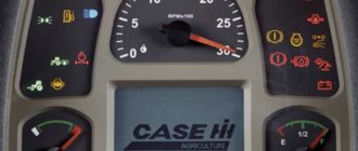
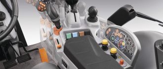
The DCU ( “Display Control Unit” or “Digital Control Unit”) is a critical component of modern Ag technology, and its primary function is to manage and display information related to the Ag equipment’s operation.
Key functions and features of a DCU may include:
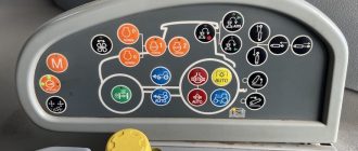
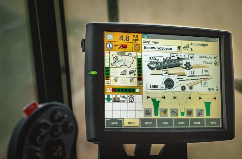
- Data Display: The DCU provides a user-friendly interface for displaying essential information to the operator. This information can include engine parameters, fuel levels, speed, hydraulic pressure, temperature, and more.
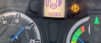
- Fault Code Display: The DCU can display Diagnostic Trouble Codes (DTCs) or fault codes when an issue or malfunction is detected in the machine’s systems. These codes help operators and technicians identify and diagnose problems quickly.
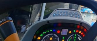
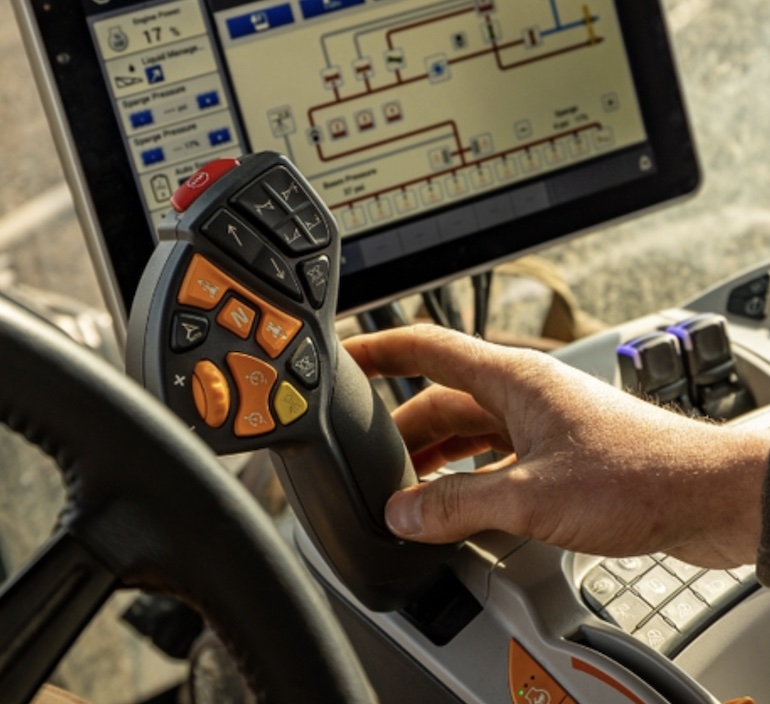
- Control Interface: In some cases, the DCU allows operators to interact with and control various equipment functions, such as adjusting engine speed, hydraulic settings, or selecting different operational modes.
- Data Logging: Many DCUs have data logging capabilities, allowing them to record and store information about agriculture equipment performance and operations. This data can be valuable for maintenance and troubleshooting.
- Connectivity: Some DCUs offer connectivity options, allowing them to communicate with other devices, such as GPS systems or farm management software, for tasks like precision farming and data analysis.
- Operator Comfort: The DCU often plays a role in enhancing operator comfort by providing climate control settings, entertainment options, and ergonomic controls.
- Safety Features: The DCU may also be linked to safety features, such as monitoring systems for rollover protection, seatbelt usage, or alerting the operator to potential safety hazards.
The specific features and capabilities of a Farming Equipment DCU can vary widely depending on the tractor’s make and model, as well as the technology integrated into the machine.
Ultimately, the DCU serves as the central hub for monitoring and controlling various aspects of equipment operation, helping operators work efficiently and safely.
New Holland & Case IH DCU Errors
Here is the table containing New Holland & Case IH DCU error code numbers along with their corresponding error descriptions:
DCU Error / Fault Codes 19001 – 19181
| Error Code Number | DCU Error Description |
|---|---|
| DCU 19001 | Battery voltage detection (electrical) – signal high – P0563 Battery voltage estimate above upper limit |
| DCU 19002 | Battery voltage detection (electrical) – signal low – P0562 Battery Voltage Evaluation Below Low Limit |
| DCU 19010 | Post Catalyst Temperature Sensor (Electrical) – High Signal – P042D High Signal in Catalyst Temperature Sensor Circuit |
| DCU 19011 | Temperature sensor after catalytic converter (electrical) – signal low – P042C Low signal in the catalyst temperature sensor circuit |
| DCU 19019 | Temperature sensor in front of the catalyst (electrical) – High signal level – P0428 High signal level in the catalyst temperature sensor circuit |
| DCU 19020 | Temperature sensor before catalytic converter (electrical) – signal low – P0427 Low signal in the catalyst temperature sensor circuit |
| DCU 19037 | Sensor supply 2 (internal 5 V; for urea pressure sensors) – Supply voltage too high – P204D Reagent – pressure sensor – short circuit, high |
| DCU 19038 | Sensor supply 2 (internal 5 V; for urea pressure sensors) – Supply voltage too low – P204C Reagent – pressure sensor – short circuit, low |
| DCU 19046 | Urea pressure sensor in box (electrical) – supply voltage error – P204A Reagent – pressure sensor – open circuit |
| DCU 19047 | Urea box pressure sensor (electrical) – signal high – P204D Reagent-pressure sensor-short circuit high |
| DCU 19048 | Urea pressure sensor in box (electrical) – signal low – P204C Reagent – pressure sensor – short circuit, low |
| DCU 19055 | Urea box temperature sensor (electrical) – signal high – P2045 Reagent – pump module temperature sensor – short circuit high |
| DCU 19056 | UREA temperature sensor in box (electrical) – signal low – P2044 Reagent – pump module temperature sensor – short circuit, low |
| DCU 19064 | Supply voltage for internal heaters 1 (UB1) electric – Open circuit to UB1 – P20C5 pump module – internal heating – open circuit |
| DCU 19065 | Supply voltage for internal heaters 1 (UB1) electric – Short to bit on UB1 with key disabled 15 – P20C8 pump module – internal heating – short circuit high |
| DCU 19073 | Power supply Two-pipe heaters (UB2) electric – Short to bit on UB2 with key disabled 15 – P20C4 Reagent – suction tube heating – short circuit high |
| DCU 19074 | Power supply Two-pipe heaters (UB2) electric – Open circuit on UB2 – P20C1 Reagent – suction tube heating – open circuit |
| DCU 19075 | Power supply Two-pipe heaters (UB2) electric – Short circuit to ground UB2 – P20C3 Reagent – Suction Tube Heated – Short circuit, low |
| DCU 19082 | Power supply 3 – Coolant control valve and check valve (UB3) electric – Short to bit on UB3 with key disabled 15 – P20A3 Vent valve (reductant purge control valve) – short circuit high |
| DCU 19083 | Power supply 3 – Coolant control valve and check valve (UB3) electric – Open circuit on UB3 – P20A0 Vent valve (reductant purge control valve) – open circuit |
| DCU 19084 | Power supply 3 – Coolant control valve and check valve (UB3) electrical – Short circuit to ground UB3 – P20A2 Vent valve (reagent purge control valve) – short circuit, low |
| DCU 19091 | Voltage control VDD11 – Dosing valve – low supply voltage – P0658 12 V power supply for the dosing module – below the lower limit |
| DCU 19092 | VDD11 voltage monitoring – dosing valve – high supply voltage – P0659 12 V supply for dosing module – above the upper limit |
| DCU 19100 | Urea level sensor (electrical) – supply voltage error – P203E Reagent level sensor – intermittent/erratic circuit |
| DCU 19101 | Urea level sensor (electrical) – signal high – P203D Reagent – tank level sensor – short circuit high |
| DCU 19102 | Urea level sensor (electrical) – signal low – P203C Reagent tank level sensor – short circuit low |
| DCU 19109 | Urea tank temperature sensor (electrical) signal high – P205D Reagent – tank temperature sensor (reagent-solution tank temperature) – short circuit high |
| DCU 19110 | Urea Tank Temperature Sensor (Electrical) – signal low – P205C Reagent – tank temperature sensor (reagent-solution tank temperature) – short circuit low |
| DCU 19145 | Dosing valve (electric) – short circuit to battery + – P2049 Reductant Injector – signal high |
| DCU 19146 | Dosing valve (electric) – short circuit to earth – P2048 Reductant Injector – circuit low |
| DCU 18147 | Dosing valve (electric) – open loading – P2047 Reductant Injector – circuit open |
| DCU 19148 | Dosing valve (electric) – Dosing valve permanently on (fast decay detection) – P209B Reagent dosing nozzle pressure too high |
| DCU 19154 | Urea pump speed – pump motor off – P208B Reagent pump not supplying |
| DCU 19155 | Urea pump speed – pump motor blocked – P208A Reagent pump |
| DCU 19156 | Urea pump speed – pump overspeed – P208D Reagent Pump Overspeed |
| DCU 19157 | Urea pump speed – Hall sensors defect – P208B Reagent pump not supplying |
| DCU 19163 | Cooling control valve short circuit to UBat or open load – short circuit to battery – P20A3 Vent valve (reductant purge control valve) – short circuit high |
| DCU 19164 | Cooling control valve short circuit to UBat or open load – Open download – P20A0 Vent valve (reductant purge control valve) – open circuit |
| DCU 19172 | Cooling control valve, short to ground – short circuit to earth – P20A2 Vent valve (reagent purge control valve) – short circuit, low |
| DCU 19181 | Check valve (4-2 way valve?) motorized – Short circuit to battery – P20A3 Vent valve (reductant purge control valve) – short circuit high |
DCU Error / Fault Codes 19182 – 19605
| Error Code Number | DCU Error Description |
|---|---|
| DCU 19182 | Check valve (4-2 way valve?) motorized – Short circuit to earth – P20A2 Vent valve (reagent purge control valve) – short circuit, low |
| DCU 19183 | Check valve (4-2 way valve?) motorized – Open download – P20A0 Vent valve (reductant purge control valve) – open circuit |
| DCU 19262 | Tank heating valve – Short circuit to battery – P20B4 Reagent – tank heating valve – short circuit high |
| DCU 19263 | Tank heating valve – Short circuit to earth – P20B3 Reagent – tank heating valve – short circuit low |
| DCU 19264 | Tank heating valve – Open download – P20B1 Reagent – tank heating valve – open circuit |
| DCU 19289 | Temperature too low after catalyst – Downstream catalyst physical temperature (catalyst heating time failure) – P042B Catalyst temperature sensor circuit range/performance |
| DCU 19298 | Urea pressure too low at system startup – Urea pressure too low at system startup – P208B Reagent Pump Not Delivering |
| DCU 19307 | Urea pressure too high – Urea pressure implausible (urea pressure too high) – P204B Reagent pressure above threshold |
| DCU 19316 | Urea temperature in pump module out of range – Urea Temperature Block – Physical (Urea Block Temp NOT OK: Out of Range) – P2043 Pump Module Reagent Temperature Sensor Out of Range |
| DCU 19325 | Urea tank temperature out of range – Urea tank temperature – physical (Urea tank temperature NOT OK: out of range) – P205B Reagent tank temperature sensor (reagent solution temperature in tank) out of range |
| DCU 19334 | System stuck and not released in time – Defrost Mode and Detection Errors (Unsuccessful Inlet Line Defrost) – P20C2 Reagent – Suction Tube Heat – Heat Detection Mode |
| DCU 19335 | The system hung and did not free itself in time – Defrost mode and detection errors (unsuccessful pressure line defrost) – P20BE Reagent – pressure tube heating – heating detection mode |
| DCU 19336 | The system hung and did not free itself in time – Defrost Mode and Detection Errors (Failed to pressurize in Detection Mode) – P20C5 pump module – internal heating – open circuit |
| DCU 19337 | The system hung and did not free itself in time – Defrost mode and detection errors (unsuccessful defrost of the reverse flow line) – P20B9 Reagent – return flow tube heating – open circuit |
| DCU 19343 | Coolant control valve mechanical – mechanical defect locked open – P20A3 Vent valve (reductant purge control valve) – short circuit high |
| DCU 19344 | Coolant control valve mechanically – mechanically failed, blocked, closed – P20A0 Vent valve (reagent purge control valve) – open circuit |
| DCU 19352 | Check valve (4-2 way valve) mechanical – valve does not open – P20A0 Vent valve (reductant purge control valve) – open circuit |
| DCU 19361 | Battery voltage (actual value) – High battery voltage – P0562 Battery Voltage Evaluation – Below Low Limit |
| DCU 19362 | Battery voltage (actual value) – Battery voltage low – P0563 Battery voltage estimate – above the upper limit |
| DCU 19370 | Urea pressure too low (in commissioning state) – Pump motor error during commissioning (pump does not pump) – P208B Reagent pump not supplying |
| DCU 19379 | UREA Commissioning temperature too low – Implausible temperatures during commissioning. |
| DCU 19415 | Urea tank empty – P203F Reagent – tank liquid level – too low |
| DCU 19532 | Return line clogged – P2063 Reagent – dosing valve – short circuit, low |
| DCU 19541 | Mechanical coolant control valve – Locked closed – P20A1 Vent Valve Test Plausibility Test (Startup) |
| DCU 19550 | Pressure line blocked – pressure line blocked – P209B Reagent-dispenser-pressure too high |
| DCU 19559 | Urea Low 1 (Warning) – Urea Below Limit 1 – Reagent P203F – Tank Fluid Level – Too Low |
| DCU 19568 | Urea Low 2 (Warning) – Urea Below Limit 2 – Reagent P203F – Tank Fluid Level – Too Low |
| DCU 19577 | CAN receive E2SCR frame (metering, exhaust gas flow, exhaust gas temperature, error suppression, heater, long-term failure) – SAE J1939 CAN Signal Reception Test: (UREA out of range) – P0600 |
| DCU 19578 | CAN receive E2SCR frame (metering, exhaust gas flow, exhaust gas temperature, error suppression, heater, long-term failure) – SAE J1939 CAN Signal Reception Test: (Dispensing Status Out of Range) – P0600 Serial communication link |
| DCU 19579 | CAN receive E2SCR frame (metering, exhaust gas flow, exhaust gas temperature, error suppression, heater, long-term failure) timeout – P0600 Serial communication link |
| DCU 19580 | CAN receive E2SCR frame (metering, exhaust gas flow, exhaust gas temperature, error suppression, heater, long-term failure) – too many CAN messages – P0600 Serial communication link |
| DCU 19581 | Receive CAN frame E2SCR (metering, exhaust gas flow, exhaust gas temperature, error suppression, heater, long-term failure) SAE J1939 CAN signal reception test – P0600 Serial communication link |
| DCU 19595 | CAN receive EEC1 frame (driver request, motor speed, motor torque) – SAE J1939 Check for CAN signal: (engine torque out of range) – P0600 Serial communication link |
| DCU 19596 | CAN receive EEC1 frame (driver request, motor speed, motor torque) – SAE J1939 CAN Signal Reception Test: (Engine RPM Out of Range) – P0600 Serial communication link |
| DCU 19597 | CAN receive EEC1 frame (driver request, motor speed, motor torque) timeout – P0600 Serial communication channel |
| DCU 19598 | CAN receive EEC1 frame (driver request, motor speed, motor torque) – too many CAN messages – P0600 Serial Communication Link |
| DCU 19599 | CAN receive EEC1 frame (driver request, motor speed, motor torque) – SAE J1939 CAN Signal Reception Test : (Torque Request Out of Range) – P0600 Serial communication link |
| DCU 19604 | CAN receives frame ET1 (engine with oil and water temperature) – SAE J1939 CAN Signal Reception Test : (Oil Temperature Out of Range) – P0600 Serial communication link |
| DCU 19605 | CAN receive frame ET1 (engine with oil and water temperature) timeout – P0600 Serial communication link |
DCU Error / Fault Codes 19606 – 19822
19818Plausibility of UDV stuck – ‘P202D Dynamic urea leakage test – Leakage
detected
| Error Code Number | DCU Error Description |
|---|---|
| DCU 19606 | CAN receives frame ET1 (engine with oil and water temperature) – too many CAN messages – P0600 Serial communication link |
| DCU 19607 | CAN receives frame ET1 (engine with oil and water temperature) – SAE J1939 CAN Signal Reception Test: (Water Temperature Out of Range) – P0600 Serial communication link |
| DCU 19649 | UREA tank level error (CAN message or electrical part with real sensor) – CAN level: SAE J1939 no Signal available Level sensor connected directly: Sensor supply error – P203A Reagent tank level sensor – open circuit |
| DCU 19650 | UREA Tank level error (CAN message or electrical with real sensor) Level above CAN: SAE J1939 Signal out of range Level sensor connected directly: SRC high – P203D Reagent – tank level sensor – short circuit high |
| DCU 19651 | UREA tank level error (CAN message or electrical with real sensor) – CAN level: SAE J1939 Faulty signal Level sensor connected directly: SRC low – P203C Reagent tank level sensor – circuit low |
| DCU 19676 | Ambient Temperature: SAE J1939 CAN Signal Reception Check: (Signal Range Check: Signal Out of Range / Bad Signal / Signal Not Available) – SAE J1939 CAN Signal Reception Test: (ambient temperature out of range) – P0600 Serial communication link |
| DCU 19677 | Ambient temperature: SAE J1939 CAN signal reception check: (Signal range check: signal out of range / signal error / signal not available) timeout – P0071 Ambient air temperature sensor range/performance |
| DCU 19678 | Ambient Temperature: SAE J1939 CAN Signal Reception Check: (Signal Range Check: Signal Out of Range / Faulty Signal / Signal Not Available) – too many CAN messages – P0071 Ambient Air Temperature Sensor Range/Performance |
| DCU 19679 | Ambient Temperature: SAE J1939 CAN Signal Reception Check: (Signal Range Check: Signal Out of Range / Faulty Signal / Signal Not Available) – SAE J1939 CAN Signal Reception Test: (Barometric Pressure Out of Range) – P0071 Ambient Air Temperature Sensor Range/Performance |
| DCU 19721 | EEPROM / Checksum Error – EEPROM write error – P062F Internal Control Module EEPROM Error |
| DCU 19722 | EEPROM / Checksum Error – No corresponding variant number error – P062F Internal Control Module EEPROM Error |
| DCU 19723 | EEPROM / Checksum Error – EEPROM communication error – P062F Internal Control Module EEPROM Error |
| DCU 19724 | EEPROM / Checksum Error – EEPROM Detection Error OR Code Error – P062F Internal Control Module EEPROM Error |
| DCU 19725 | EEPROM / Checksum Error – Wrong EEPROM size – P062F Internal Control Module EEPROM Error |
| DCU 19730 | Ignition switch signal K15 – ignition on digital input not detected during initialization – P2530 Ignition lock – plausibility error |
| DCU 19739 | Main relay opens too early/too late – main relay cuts out too late – P0687 ECM/PCM Power Relay Control Circuit High |
| DCU 19740 | Main relay opens too early/too late – short circuit of the main relay – P0685 ECM/PCM Power Relay Control Circuit / Open |
| DCU 19741 | Main relay opens too early/too late – main relay circuit open – P0687 ECM/PCM Power Relay Control Circuit High |
| DCU 19742 | Main Relay Opens Too Early/Too Late Main Relay Opens Too Early (Before EEPROM Update) – P0685 ECM/PCM Power Relay Control Circuit/Open |
| DCU 19748 | Urea Pump Module Temperature Too High or Leak Test Failed (Emergency Shutdown) – Over Temperature Detection (Urea Pump Module Temperature) – P2043 Pump Module Reagent Temperature Sensor Out of Range |
| DCU 19749 | Pump module urea temperature too high or leak test failed (safety shutdown) – urea leak detection (static or dynamic) – P202D Urea Dynamic Leak Test – Leak Detected |
| DCU 19757 | Injection Control Path Group Error – UREA Injection Control Group Related Error UREA – P208B Reagent Pump Not Delivering |
| DCU 19766 | Group error path Air control – Group air control related error – P20A7 Compressed air control valve |
| DCU 19775 | Catalyst Temperature Path Group Error – Group Related Error Catalyst Temperature Out of Range – P0426 Catalyst Temperature Sensor Plausibility – Plausibility Error (static) |
| DCU 19784 | NOx group error path exceeded – NOx group related error exceeded active – P2000 NOx trap efficiency below threshold |
| DCU 19793 | Group error path Urea tank empty – Group related error Urea tank empty active – P203F Reagent tank liquid level too low |
| DCU 19793 | Group error path UREA Tank empty – Error belonging to group UREA tank empty active – P203F Reagent – fluid level in tank – Too low |
| DCU 19802 | SAE J1939 Timeout Temp sensor connected directly: SRC high – P0600 Serial Communication Link |
| DCU 19803 | SAE J1939 Too many messages Temp sensor connected directly: SRC low – P0600 Serial Communication Link |
| DCU 19804 | SAE J1939 erroneous signal – P205A Reagent – tank temperature sensor (temperature of the Reagent – solution in the tank) – Open circuit |
| DCU 19805 | SRC High: raw value UREA temperature too high – P205D Reagent – tank temperature sensor (temperature of the Reagent – solution in the tank) – Short circuit high |
| DCU 19806 | SRC Low: raw value UREA temperature too low – P205C Reagent – tank temperature sensor (temperature of the Reagent – solution in the tank) – Short circuit low |
| DCU 19807 | SRC High: diagnostic value UREA temperature too high – P205B Reagent – tank temperature sensor (temperature of the Reagent – solution in the tank) – Out of range |
| DCU 19808 | SRC Low: diagnostic value UREA temperature too low – P205B Reagent – tank temperature sensor (temperature of the Reagent – solution in the tank) – Out of range |
| DCU 19813 | Startup cycle counter for pressure drop during dosing – P208B Reagent-pump – Not delivering |
| DCU 19817 | Plausibility of UDV stuck – P202F Reagent – dosing valve – Blocked (only stuck closed) |
| DCU 19822 | UDV valve stuck position unknown error – P202D Dynamic urea leakage test – Leakage detected |
Can I Clear New Holland & Case IH DCU Errors Myself?
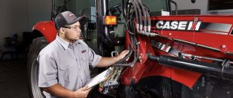
Clearing Diagnostic Control Unit (DCU) errors on New Holland and Case IH tractors may not be a straightforward process and typically requires specialized tools and knowledge. DCU errors are crucial indicators of potential issues within the tractor’s systems, and clearing them without addressing the root cause could lead to persistent problems.
Here are some considerations if you are contemplating clearing DCU errors yourself:
- Refer to the Manual: Consult the tractor’s service manual for information about DCU errors, their meanings, and any recommended troubleshooting steps. The manual will provide specific guidance related to your tractor model.
- Address Underlying Issues: Before attempting to clear DCU errors, identify and address any underlying issues causing the codes. Clearing codes without resolving the problem may lead to ongoing malfunctions.
- Use Diagnostic Tools: Specialized diagnostic tools, often specific to the manufacturer, may be required to clear DCU errors. If you have access to such tools, follow the manufacturer’s instructions for code clearing procedures.
- Disconnect Battery: Disconnecting the tractor’s battery for a short period may reset the electronic control systems and clear some errors. However, this method may not work for all models, and it’s essential to check the manual.
- Seek Professional Assistance: If you are unsure about how to clear DCU errors or if you are unable to resolve the underlying issue, it’s advisable to seek assistance from a certified Case IH or New Holland mechanic or an authorized service center. They have the expertise to diagnose and address problems properly.
Clearing error codes without addressing the root cause may lead to ongoing issues. It’s crucial to follow the manufacturer’s guidelines, use appropriate diagnostic tools, and ensure that any underlying problems are resolved. If you lack the necessary tools or expertise, involving professionals is the safest and most effective approach when working on your tractor’s DCU system. Always prioritize safety and adhere to manufacturer guidelines when performing maintenance or troubleshooting.
How Can I Prevent New Holland & Case IH DCU Errors?
Preventing Diagnostic Control Unit (DCU) errors on New Holland and Case IH tractors involves a combination of regular maintenance, proper operation, and proactive troubleshooting. Here are some tips to help prevent DCU errors:
- Regular Maintenance: Follow the manufacturer’s recommended maintenance schedule outlined in the tractor’s service manual. Regularly inspect and maintain all components related to the electronic control systems, ensuring that they are in good condition.
- Operate within Specifications: Operate the tractor within the specified load capacities and operational parameters outlined in the user manual. Avoid exceeding the limits of the tractor’s systems, as this can lead to stress and potential errors.
- Use Quality Fuel and Lubricants: Ensure that you are using high-quality fuel and lubricants recommended by the manufacturer. Poor-quality fuel or lubricants can lead to issues with the engine and electronic control systems.
- Calibrate Sensors: If your tractor is equipped with sensors related to various systems, ensure they are calibrated according to the manufacturer’s guidelines. Accurate sensor readings are crucial for proper system function.
- Monitor Warning Lights: Pay attention to warning lights or indicators on the tractor’s dashboard. If any warning lights illuminate, address the issue promptly rather than continuing to operate the tractor with potential problems.
- Check Electrical Connections: Regularly inspect electrical connections, wires, and harnesses for signs of wear, corrosion, or damage. Ensure that all connections are secure, and address any issues promptly.
- Protect from Environmental Factors: Shield the tractor from extreme weather conditions, especially when not in use. Moisture, excessive heat, and other environmental factors can contribute to electronic system issues.
- Proper Shutdown Procedures: Follow proper shutdown procedures outlined in the manual. Avoid abrupt stops or shutting down the tractor without allowing the electronic control systems to settle properly.
- Keep Software Updated: If your tractor’s electronic control systems rely on software, keep it updated to the latest version provided by the manufacturer. Software updates may include improvements and bug fixes.
- Professional Inspections: Schedule regular inspections by certified technicians. Professionals can identify and address potential issues before they lead to errors.
- Operator Training: Ensure that tractor operators are trained on proper usage, maintenance, and troubleshooting procedures related to the electronic control systems. Knowledgeable operators are more likely to detect and prevent issues.
By implementing these preventive measures, you can reduce the likelihood of DCU errors on your Case IH and New Holland tractors. Regular maintenance, adherence to operational guidelines, and proactive attention to potential issues contribute to the overall reliability and performance of the tractor’s electronic control systems.
DTC Fault Code Lists of New Holland & Case IH Tractors:
- Armrest Errors
- ATC Error Codes
- Auxiliary Remote Valve Errors
- Engine Error Codes
- Front PTO Error Codes
- Hitch Error Codes
- Instrument Control Unit Errors
- INST Error Codes
- MFD/Diff List of Errors
- Multifunction Controller Errors
- Rear PTO Error Codes
- Suspension Errors
- Transmission Error Codes
- FAQ for CNH Industrial DTCs