Wire gauge charts provide a reference for determining the diameter or thickness of wires, typically used in electrical and engineering applications. These charts are available for various wire gauge standards, including the American Wire Gauge (AWG), Standard Wire Gauge (SWG), and others. They display the gauge number alongside the corresponding diameter or thickness in inches or millimeters. Wire gauge charts are invaluable tools for selecting the appropriate wire size for specific purposes, ensuring compatibility and safety in electrical systems and other applications.
American Wire Gauge Size Chart (AWG)
The American Wire Gauge (AWG) is a standardized wire gauge system introduced in 1857, primarily utilized in North America to specify the diameters of round, solid, nonferrous, electrically conducting wires.
| AWG | Diameter | Turns of wire, w/o insulation | Area | |||
|---|---|---|---|---|---|---|
| (in) | (mm) | (per in) | (per cm) | (kcmil) | (mm2) | |
| 0000 (4/0) | 0.4600 | 11.684 | 2.17 | 0.856 | 212 | 107 |
| 000 (3/0) | 0.4096 | 10.405 | 2.44 | 0.961 | 168 | 85.0 |
| 00 (2/0) | 0.3648 | 9.266 | 2.74 | 1.08 | 133 | 67.4 |
| 0 (1/0) | 0.3249 | 8.251 | 3.08 | 1.21 | 106 | 53.5 |
| 1 | 0.2893 | 7.348 | 3.46 | 1.36 | 83.7 | 42.4 |
| 2 | 0.2576 | 6.544 | 3.88 | 1.53 | 66.4 | 33.6 |
| 3 | 0.2294 | 5.827 | 4.36 | 1.72 | 52.6 | 26.7 |
| 4 | 0.2043 | 5.189 | 4.89 | 1.93 | 41.7 | 21.2 |
| 5 | 0.1819 | 4.621 | 5.50 | 2.16 | 33.1 | 16.8 |
| 6 | 0.1620 | 4.115 | 6.17 | 2.43 | 26.3 | 13.3 |
| 7 | 0.1443 | 3.665 | 6.93 | 2.73 | 20.8 | 10.5 |
| 8 | 0.1285 | 3.264 | 7.78 | 3.06 | 16.5 | 8.37 |
| 9 | 0.1144 | 2.906 | 8.74 | 3.44 | 13.1 | 6.63 |
| 10 | 0.1019 | 2.588 | 9.81 | 3.86 | 10.4 | 5.26 |
| 11 | 0.0907 | 2.305 | 11.0 | 4.34 | 8.23 | 4.17 |
| 12 | 0.0808 | 2.053 | 12.4 | 4.87 | 6.53 | 3.31 |
| 13 | 0.0720 | 1.828 | 13.9 | 5.47 | 5.18 | 2.62 |
| 14 | 0.0641 | 1.628 | 15.6 | 6.14 | 4.11 | 2.08 |
| 15 | 0.0571 | 1.450 | 17.5 | 6.90 | 3.26 | 1.65 |
| 16 | 0.0508 | 1.291 | 19.7 | 7.75 | 2.58 | 1.31 |
| 17 | 0.0453 | 1.150 | 22.1 | 8.70 | 2.05 | 1.04 |
| 18 | 0.0403 | 1.024 | 24.8 | 9.77 | 1.62 | 0.823 |
| 19 | 0.0359 | 0.912 | 27.9 | 11.0 | 1.29 | 0.653 |
| 20 | 0.0320 | 0.812 | 31.3 | 12.3 | 1.02 | 0.518 |
| 21 | 0.0285 | 0.723 | 35.1 | 13.8 | 0.810 | 0.410 |
| 22 | 0.0253 | 0.644 | 39.5 | 15.5 | 0.642 | 0.326 |
| 23 | 0.0226 | 0.573 | 44.3 | 17.4 | 0.509 | 0.258 |
| 24 | 0.0201 | 0.511 | 49.7 | 19.6 | 0.404 | 0.205 |
| 25 | 0.0179 | 0.455 | 55.9 | 22.0 | 0.320 | 0.162 |
| 26 | 0.0159 | 0.405 | 62.7 | 24.7 | 0.254 | 0.129 |
| 27 | 0.0142 | 0.361 | 70.4 | 27.7 | 0.202 | 0.102 |
| 28 | 0.0126 | 0.321 | 79.1 | 31.1 | 0.160 | 0.0810 |
| 29 | 0.0113 | 0.286 | 88.8 | 35.0 | 0.127 | 0.0642 |
| 30 | 0.0100 | 0.255 | 99.7 | 39.3 | 0.101 | 0.0509 |
| 31 | 0.00893 | 0.227 | 112 | 44.1 | 0.0797 | 0.0404 |
| 32 | 0.00795 | 0.202 | 126 | 49.5 | 0.0632 | 0.0320 |
| 33 | 0.00708 | 0.180 | 141 | 55.6 | 0.0501 | 0.0254 |
| 34 | 0.00630 | 0.160 | 159 | 62.4 | 0.0398 | 0.0201 |
| 35 | 0.00561 | 0.143 | 178 | 70.1 | 0.0315 | 0.0160 |
| 36 | 0.00500 | 0.127 | 200 | 78.7 | 0.0250 | 0.0127 |
| 37 | 0.00445 | 0.113 | 225 | 88.4 | 0.0198 | 0.0100 |
| 38 | 0.00397 | 0.101 | 252 | 99.3 | 0.0157 | 0.00797 |
| 39 | 0.00353 | 0.0897 | 283 | 111 | 0.0125 | 0.00632 |
| 40 | 0.00314 | 0.0799 | 318 | 125 | 0.00989 | 0.00501 |
The wire dimensions are outlined in ASTM standard B 258, with the cross-sectional area of each gauge serving as a critical determinant of its current-carrying capacity.
AWG employs a logarithmic stepped scale, with increasing gauge numbers corresponding to logarithmically decreasing wire diameters. This logarithmic progression aligns with other non-metric gauging systems like the British Standard Wire Gauge (SWG). However, AWG differs from the metric wire-size standard, IEC 60228, prevalent in most global regions, which bases measurements directly on the wire cross-sectional area in square millimeters (mm²).
AWG Chart for Copper Wire (Resistance / Ampacity / Fusing Current)
The following table presents diverse data, encompassing the resistance of different wire gauges and the permissible current (ampacity) for copper conductors with plastic insulation. The diameter specifications provided pertain to solid wires; for stranded wires, the equivalent cross-sectional copper area is computed.
Fusing current, indicative of the wire’s melting point, is approximated at a 25°C (77°F) ambient temperature. The table’s assumptions are based on DC currents or AC frequencies at or below 60 Hz, without factoring in the skin effect phenomenon.
| AWG Copper wire | Length-specific resistance | Ampacity at temperature rating | Fusing current | |||||
|---|---|---|---|---|---|---|---|---|
| 60 °C | 75 °C | 90 °C | Preece | Onderdonk | ||||
| (mΩ/m) | (mΩ/ft) | (A) | ~10 s | 1 s | 32 ms | |||
| 0000 (4/0) | 0.1608 | 0.0490 | 195 | 230 | 260 | 3.2 kA | 33 kA | 182 kA |
| 000 (3/0) | 0.2028 | 0.0618 | 165 | 200 | 225 | 2.7 kA | 26 kA | 144 kA |
| 00 (2/0) | 0.2557 | 0.0779 | 145 | 175 | 195 | 2.3 kA | 21 kA | 115 kA |
| 0 (1/0) | 0.3224 | 0.0982 | 125 | 150 | 170 | 1.9 kA | 16 kA | 91 kA |
| 1 | 0.4066 | 0.1239 | 110 | 130 | 145 | 1.6 kA | 13 kA | 72 kA |
| 2 | 0.5127 | 0.1563 | 95 | 115 | 130 | 1.3 kA | 10.2 kA | 57 kA |
| 3 | 0.6465 | 0.1970 | 85 | 100 | 115 | 1.1 kA | 8.1 kA | 45 kA |
| 4 | 0.8152 | 0.2485 | 70 | 85 | 95 | 946 A | 6.4 kA | 36 kA |
| 5 | 1.028 | 0.3133 | 795 A | 5.1 kA | 28 kA | |||
| 6 | 1.296 | 0.3951 | 55 | 65 | 75 | 668 A | 4.0 kA | 23 kA |
| 7 | 1.634 | 0.4982 | 561 A | 3.2 kA | 18 kA | |||
| 8 | 2.061 | 0.6282 | 40 | 50 | 55 | 472 A | 2.5 kA | 14 kA |
| 9 | 2.599 | 0.7921 | 396 A | 2.0 kA | 11 kA | |||
| 10 | 3.277 | 0.9989 | 30 | 35 | 40 | 333 A | 1.6 kA | 8.9 kA |
| 11 | 4.132 | 1.260 | 280 A | 1.3 kA | 7.1 kA | |||
| 12 | 5.211 | 1.588 | 20 | 25 | 30 | 235 A | 1.0 kA | 5.6 kA |
| 13 | 6.571 | 2.003 | 198 A | 798 A | 4.5 kA | |||
| 14 | 8.286 | 2.525 | 15 | 20 | 25 | 166 A | 633 A | 3.5 kA |
| 15 | 10.45 | 3.184 | 140 A | 502 A | 2.8 kA | |||
| 16 | 13.17 | 4.016 | 18 | 117 A | 398 A | 2.2 kA | ||
| 17 | 16.61 | 5.064 | 99 A | 316 A | 1.8 kA | |||
| 18 | 20.95 | 6.385 | 10 | 14 | 16 | 83 A | 250 A | 1.4 kA |
| 19 | 26.42 | 8.051 | — | — | — | 70 A | 198 A | 1.1 kA |
| 20 | 33.31 | 10.15 | 5 | 11 | — | 58.5 A | 158 A | 882 A |
| 21 | 42.00 | 12.80 | — | — | — | 49 A | 125 A | 700 A |
| 22 | 52.96 | 16.14 | 3 | 7 | — | 41 A | 99 A | 551 A |
| 23 | 66.79 | 20.36 | — | — | — | 35 A | 79 A | 440 A |
| 24 | 84.22 | 25.67 | 2.1 | 3.5 | — | 29 A | 62 A | 348 A |
| 25 | 106.2 | 32.37 | — | — | — | 24 A | 49 A | 276 A |
| 26 | 133.9 | 40.81 | 1.3 | 2.2 | — | 20 A | 39 A | 218 A |
| 27 | 168.9 | 51.47 | — | — | — | 17 A | 31 A | 174 A |
| 28 | 212.9 | 64.90 | 0.83 | 1.4 | — | 14 A | 24 A | 137 A |
| 29 | 268.5 | 81.84 | — | — | — | 12 A | 20 A | 110 A |
| 30 | 338.6 | 103.2 | 0.52 | 0.86 | — | 10 A | 15 A | 86 A |
| 31 | 426.9 | 130.1 | — | — | — | 9 A | 12 A | 69 A |
| 32 | 538.3 | 164.1 | 0.32 | 0.53 | — | 7 A | 10 A | 54 A |
| 33 | 678.8 | 206.9 | — | — | — | 6 A | 7.7 A | 43 A |
| 34 | 856.0 | 260.9 | 0.18 | 0.3 | — | 5 A | 6.1 A | 34 A |
| 35 | 1079 | 329.0 | — | — | — | 4 A | 4.8 A | 27 A |
| 36 | 1361 | 414.8 | — | — | — | 4 A | 3.9 A | 22 A |
| 37 | 1716 | 523.1 | — | — | — | 3 A | 3.1 A | 17 A |
| 38 | 2164 | 659.6 | — | — | — | 3 A | 2.4 A | 14 A |
| 39 | 2729 | 831.8 | — | — | — | 2 A | 1.9 A | 11 A |
| 40 | 3441 | 1049 | — | — | — | 1 A | 1.5 A | 8.5 A |
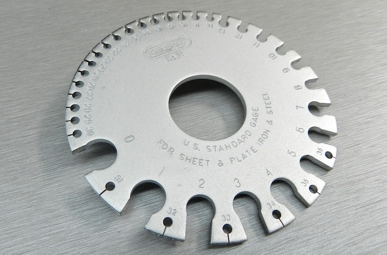
While AWG and the Brown & Sharpe (B&S) sheet metal gauge are essentially identical, the latter was specifically designed for use with sheet metals, despite their functional interchangeability. The use of B&S terminology in reference to wire gauges is technically incorrect.
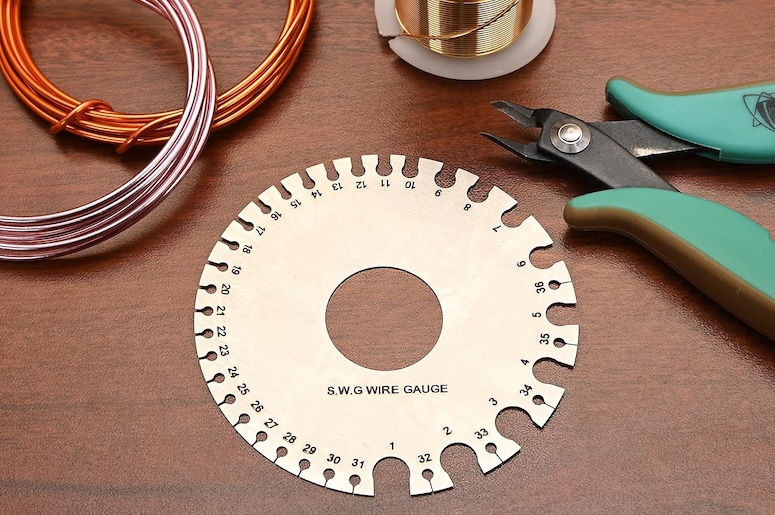
British Standard Wire Gauge Size Chart (SWG)
Below is a table listing gauge numbers alongside corresponding wire diameters. The system is based on the “thou” (or “mil” in US English), equivalent to 0.001 inches. Wire sizes are denoted as diameters in thou and tenths of a thou (mils and tenths). As gauge numbers increase, wire diameter decreases. For instance, the largest size, No. 7/0, measures 0.50 inches (500 thou or 12.7 mm) in diameter, while No. 1 is 0.30 inches (300 thou), and the smallest, No. 50, is 0.001 inches (1 thou or 25.4 µm).
The system exhibits an approximate exponential curve when plotting diameter against gauge number, with each size being roughly a constant multiple of the preceding size. The weight per unit length decreases by an average of about 20% with each step.
| SWG | Diameter (in) | Diameter (mm) | Step |
|---|---|---|---|
| 7/0 | 0.500 | 12.700 | 0.036″/gauge |
| 6/0 | 0.464 | 11.786 | 0.032″/gauge |
| 5/0 | 0.432 | 10.973 | |
| 4/0 | 0.400 | 10.160 | 0.028″/gauge |
| 3/0 | 0.372 | 9.449 | 0.024″/gauge |
| 2/0 | 0.348 | 8.839 | |
| 0 | 0.324 | 8.230 | |
| 1 | 0.300 | 7.620 | |
| 2 | 0.276 | 7.010 | |
| 3 | 0.252 | 6.401 | 0.020″/gauge |
| 4 | 0.232 | 5.893 | |
| 5 | 0.212 | 5.385 | |
| 6 | 0.192 | 4.877 | 0.016″/gauge |
| 7 | 0.176 | 4.470 | |
| 8 | 0.160 | 4.064 | |
| 9 | 0.144 | 3.658 | |
| 10 | 0.128 | 3.251 | 0.012″/gauge |
| 11 | 0.116 | 2.946 | |
| 12 | 0.104 | 2.642 | |
| 13 | 0.092 | 2.337 | |
| 14 | 0.080 | 2.032 | 0.008″/gauge |
| 15 | 0.072 | 1.829 | |
| 16 | 0.064 | 1.626 | |
| 17 | 0.056 | 1.422 | |
| 18 | 0.048 | 1.219 | |
| 19 | 0.040 | 1.016 | 0.004″/gauge |
| 20 | 0.036 | 0.914 | |
| 21 | 0.032 | 0.813 | |
| 22 | 0.028 | 0.711 | |
| 23 | 0.024 | 0.610 | 0.002″/gauge |
| 24 | 0.022 | 0.559 | |
| 25 | 0.020 | 0.5080 | |
| 26 | 0.018 | 0.4572 | 0.0016″/gauge |
| 27 | 0.0164 | 0.4166 | |
| 28 | 0.0148 | 0.3759 | 0.0012″/gauge |
| 29 | 0.0136 | 0.3454 | |
| 30 | 0.0124 | 0.3150 | 0.0008″/gauge |
| 31 | 0.0116 | 0.2946 | |
| 32 | 0.0108 | 0.2743 | |
| 33 | 0.0100 | 0.2540 | |
| 34 | 0.0092 | 0.2337 | |
| 35 | 0.0084 | 0.2134 | |
| 36 | 0.0076 | 0.1930 | |
| 37 | 0.0068 | 0.1727 | |
| 38 | 0.0060 | 0.1524 | |
| 39 | 0.0052 | 0.1321 | 0.0004″/gauge |
| 40 | 0.0048 | 0.1219 | |
| 41 | 0.0044 | 0.1118 | |
| 42 | 0.004 | 0.1016 | |
| 43 | 0.0036 | 0.0914 | |
| 44 | 0.0032 | 0.0813 | |
| 45 | 0.0028 | 0.0711 | |
| 46 | 0.0024 | 0.0610 | |
| 47 | 0.0020 | 0.0508 | |
| 48 | 0.0016 | 0.0406 | |
| 49 | 0.0012 | 0.0305 | 0.0002″/gauge |
| 50 | 0.0010 | 0.0254 |
Since weight per unit length is proportional to the cross-sectional area, which in turn is related to the square of the diameter, the diameter decreases by approximately 10.6%. However, the system is piecewise linear and only loosely approximates the exponential curve. It progresses in constant steps of 0.4 thou (0.4 mil) within the range of No. 49 to No. 39, and 0.8 thou (0.8 mil) from No. 39 to No. 30.
Comparison of AWG & IEC Wire Gauge Sizes
American Wire Gauge (AWG) and IEC 60228 (mm2) wire sizes.
| AWG | IEC (mm2) |
|---|---|
| 30 | 0.05 |
| 28 | 0.08 |
| 26 | 0.14 |
| 24 | 0.25 |
| 22 | 0.34 |
| 21 | 0.38 |
| 20 | 0.50 |
| 18 | 0.75 |
| 17 | 1.00 |
| 16 | 1.50 |
| 14 | 2.50 |
| 12 | 4 |
| 10 | 6 |
| 8 | 10 |
| 6 | 16 |
| 4 | 25 |
| 2 | 35 |
| 1 | 50 |
| 2/0 | 70 |
| 3/0 | 95 |
| 4/0 | 120 |
| 300 MCM | 150 |
| 350 MCM | 185 |
| 500 MCM | 240 |
| 600 MCM | 300 |
| 750 MCM | 400 |
| 1000 MCM | 500 |
Strand make-up according to DIN VDE 0295, IEC 60228
| Cross-section in mm² | Stranded Wires | Multi-Stranded Wires | Fine Wires | Extra-fine Wires | |||
| class 2 DIN VDE 0295 | class 5 DIN VDE 0295 | class 6 DIN VDE 0295 | |||||
| Number*** of Wires x Single Wire Ø in mm | Number of Wires x Single Wire Ø in mm | Number* of Wires** x Single Wire Ø in mm | Number* of Wires** x Single Wire Ø in mm | Number* of Wires x Single Wire Ø in mm | Number* of Wires x Single Wire Ø in mm | Number* of Wires x Single Wire Ø in mm | |
| 0.05 | ~14 x 0.07 | ~26 x 0.05 | |||||
| 0.08 | ~40 x 0.05 | ||||||
| 0.09 | ~24 x 0.07 | ||||||
| 0.14 | ~18 x 0.1 | ~18 x 0.1 | ~18 x 0.1 | ~36 x 0.07 | ~72 x 0.05 | ||
| 0.25 | ~14 x 0.15 | ~32 x 0.1 | ~32 x 0.1 | ~65 x 0.07 | ~128 x 0.05 | ||
| 0.34 | 7 x 0.25 | ~19 x 0.15 | ~42 x 0.1 | ~42 x 0.1 | ~88 x 0.07 | ~174 x 0.05 | |
| 0.38 | 7 x 0.27 | ~12 x 0.2 | ~21 x 0.15 | ~48 x 0.1 | ~100 x 0.07 | ~194 x 0.05 | |
| 0.5 | 7 x 0.30 | 7 x 0.30 | ~16 x 0.2 | ~28 x 0.15 | ~64 x 0.1 | ~131 x 0.07 | ~256 x 0.05 |
| 0.75 | 7 x 0.37 | 7 x 0.37 | ~24 x 0.2 | ~42 x 0.15 | ~96 x 0.1 | ~195 x 0.07 | ~384 x 0.05 |
| 1.0 | 7 x 0.43 | 7 x 0.43 | ~32 x 0.2 | ~56 x 0.15 | ~128 x 0.1 | ~260 x 0.07 | ~512 x 0.05 |
| 1.5 | 7 x 0.52 | 7 x 0.52 | ~30 x 0.25 | ~84 x 0.15 | ~192 x 0.1 | ~392 x 0.07 | ~768 x 0.05 |
| 2.5 | 7 x 0.67 | 19 x 0.41 | ~50 x 0.25 | ~140 x 0.15 | ~320 x 0.1 | ~651 x 0.07 | ~1280 x 0.05 |
| 4 | 7 x 0.85 | 19 x 0.52 | ~56 x 0.3 | ~224 x 0.15 | ~512 x 0.1 | ~1040 x 0.07 | |
| 6 | 7 x 1.05 | 19 x 0.64 | ~84 x 0.3 | ~192 x 0.2 | ~768 x 0.1 | ~1560 x 0.07 | |
| 10 | 7 x 1.35 | 49 x 0.51 | ~80 x 0.4 | ~320 x 0.2 | ~1280 x 0.1 | ~2600 x 0.07 | |
| 16 | 7 x 1.70 | 49 x 0.65 | ~128 x 0.4 | ~512 x 0.2 | ~2048 x 0.1 | ||
| 25 | 7 x 2.13 | 84 x 0.62 | ~200 x 0.4 | ~800 x 0.2 | ~3200 x 0.1 | ||
| 35 | 7 x 2.52 | 133 x 0.58 | ~280 x 0.4 | ~1120 x 0.2 | |||
| 50 | 19 x 1.83 | 133 x 0.69 | ~400 x 0.4 | ~705 x 0.3 | |||
| 70 | 19 x 2.17 | 189 x 0.69 | ~356 x 0.5 | ~990 x 0.3 | |||
| 95 | 19 x 2.52 | 259 x 0.69 | ~485 x 0.5 | ~1340 x 0.3 | |||
| 120 | 37 x 2.03 | 336 x 0.67 | ~614 x 0.5 | ~1690 x 0.3 | |||
| 150 | 37 x 2.27 | 392 x 0.69 | ~765 x 0.5 | ~2123 x 0.3 | |||
| 185 | 37 x 2.52 | 494 x 0.69 | ~944 x 0.5 | ~1470 x 0.4 | |||
| 240 | 61 x 2.24 | 627 x 0.70 | ~1225 x 0.5 | ~1905 x 0.4 | |||
| 300 | 61 x 2.50 | 790 x 0.70 | ~1530 x 0.5 | ~2385 x 0.4 | |||
| 400 | 61 x 2.89 | ~2035 x 0.5 | |||||
| 500 | 61 x 3.23 | ~1768 x 0.6 | |||||
| 630 | 91 x 2.97 | ~2228 x 0.6 | |||||
* The number of individual wires are without obligation.
** The diameters of the single wires for each conductor are not allowed to exceed the values stated to DIN VDE 0295. The single wires of a stranded conductor must have all the same nominal diameters.
*** Minimum-number of single wires of stranded conductor. The single wires of a stranded conductor must have all the same nominal diameters.
Visual Comparison of AWG, SWG & IEC Wire Gauge Sizes
Below is a comparison of wire gauge sizes according to the British Standard Wire Gauge (SWG), American Wire Gauge (AWG), and International Electrotechnical Commission (IEC) 60228 standard. Note that the gauge numbers and corresponding wire diameters may vary slightly depending on the specific standard or application.
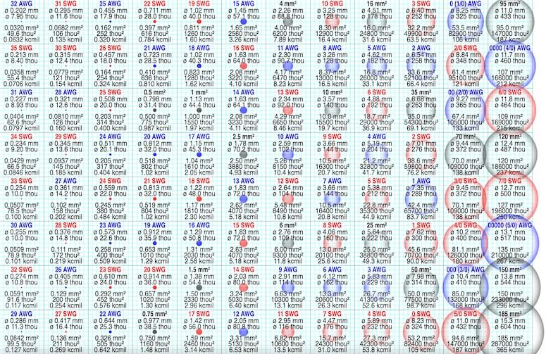
Comparison of SWG (red), AWG (blue) and IEC 60228 (black) wire gauge sizes from 0.03 to 200 mm2 to scale on a 1 mm grid (in the SVG file, hover over a size to highlight it). SWG and AWG are commonly used in the UK and US, respectively, while IEC 60228 is an international standard.


Does this data depend heavily on the wire material? For example, what if I choose aluminum wire rather than copper?
For different types of wires and materials, the dimensions may vary, for example for multi-core cables!