- What is Case IH DTC Fault Codes?
- List of Case IH Tractor DTC Fault Codes
- Case IH Fault Codes from 1000 to 2000
- Case IH Fault Codes from 2000 to 3000
- Case IH Fault Codes from 3000 to 4000
- Case IH Fault Codes from 4000 to 5000
- Case IH Fault Codes from 5000 to 16000
- Case IH Calibration Codes from U1 to U89
- Understanding Case IH Tractor Error / Fault Codes
- How to Interpret Case IH Tractor Error Codes:
- Common Case IH Tractor Error Codes:
- Benefits of Understanding DTCs:
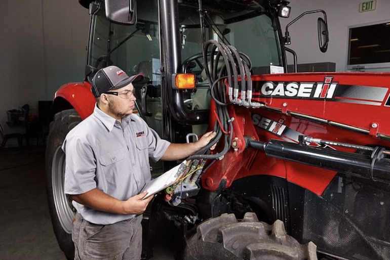
Understanding and diagnosing error or fault codes in Case IH tractors is crucial for ensuring optimal performance and minimizing downtime. Case IH tractors are equipped with sophisticated electronic systems that monitor various components and systems. When an issue arises, the onboard diagnostics generate error or fault codes to help identify the problem.
In this guide, we’ll delve into the comprehensive list of Case IH tractor error codes, providing insights into their meanings and possible causes. Whether you’re troubleshooting engine-related issues, hydraulic malfunctions, or electrical problems, having a solid understanding of the error codes is essential for efficient and effective repairs. We’ll cover everything from common diagnostic trouble codes (DTCs) to more specific issues unique to Case IH tractors. By the end of this guide, you’ll be well-equipped to interpret error codes, pinpoint the root cause of problems, and implement the necessary repairs. Let’s dive into the world of Case IH tractor diagnostics and empower you with the knowledge needed to keep these powerful machines running smoothly in the field.
What is Case IH DTC Fault Codes?
Case IH DTC Fault Codes are alphanumeric codes generated by the tractor’s onboard diagnostic system. These Diagnostic Trouble Codes (DTC) provide information about specific issues or malfunctions within various systems of the tractor. When a problem is detected, the system assigns a unique code, which can then be read using diagnostic tools to identify and troubleshoot the underlying problem. Tractor DTC Fault Codes cover a wide range of systems, including the engine, transmission, hydraulics, and more. Each code corresponds to a specific fault or condition, helping technicians and operators diagnose issues efficiently. When a fault occurs, the corresponding DTC is stored in the tractor’s memory, enabling users to access valuable diagnostic information.
It’s important to note that interpreting DTC Fault Codes requires reference to the specific Case IH tractor model’s service manual or documentation, as codes can vary between models and series. Trained technicians often use specialized diagnostic tools to read and interpret these codes, allowing for accurate identification of issues and timely resolution. In summary, Case IH Tractor Fault Codes are a diagnostic tool that aids in identifying and addressing potential problems within the tractor’s systems, contributing to efficient maintenance and minimizing downtime.
List of Case IH Tractor DTC Fault Codes
Here’s the complete table with all the error codes and their descriptions:
Case IH Fault Codes from 1000 to 2000
| Error Code | Error / Fault Code Description |
|---|---|
| 1002 | Radar disabled |
| 1003 | Speed Sensor Error |
| 1004 | Speed sensor signal too high |
| 1005 | Speed sensor signal too high |
| 1006 | Slip control potentiometer signal too low |
| 1007 | Slip control potentiometer signal too high |
| 1008 | Lift/Run Switch Malfunction |
| 1009 | Both external switches tripped at the same time |
| 1010 | Height limit potentiometer too low |
| 1011 | Height limit potentiometer signal too high |
| 1012 | Fall rate potentiometer signal too low |
| 1013 | Fall rate potentiometer signal too high |
| 1014 | R/H load cell signal too weak |
| 1015 | R/H load cell signal too high |
| 1016 | L/H load cell signal too weak |
| 1017 | L/H load cell signal too high |
| 1018 | Both load cells disconnected |
| 1019 | Load cell voltage too low |
| 1020 | Load cell voltage too high |
| 1021 | Position/Thrust Control Potentiometer Too Low |
| 1022 | Position/Thrust Control Potentiometer Too High |
| 1023 | Control panel disabled |
| 1024 | Perform Hydraulic Lift Auto Calibration |
| 1025 | Mouse lift lever potentiometer signal too low |
| 1026 | Mouse lift lever potentiometer signal too high |
| 1027 | Maximum Lift arm position potentiometer too low |
| 1028 | Maximum Lift arm position potentiometer too high |
| 1029 | Hydraulic Control Valve Disabled |
| 1030 | Ground signal open circuit (not used) |
| 1031 | Chassis wiring harness disconnected |
| 1032 | Traction load potentiometer shorted to +12V |
| 1033 | Traction Load Potentiometer Open Circuit |
| 1049 | Wheel speed sensor circuit open |
| 1053 | 5V link, shorted to +12V |
| 1054 | Reference voltage 5 V Short to ground. |
| 1057 | Module failure (not in use) |
| 1059 | 5 volt reference open circuit (not used) |
| 1063 | Lower Solenoid Circuit Open |
| 1064 | Lift Solenoid Circuit Open |
| 1065 | Lower Solenoid Shorted |
| 1066 | Short circuit of the lift solenoid |
| 1067 | EDC hydraulic valve flow too low |
| 1068 | Height limit Calibration error |
Case IH Fault Codes from 2000 to 3000
| Error Code | Error / Fault Code Description |
|---|---|
| 2001 | ‘N’ – Shuttle too fast error |
| 2002 | Flash N error |
| 2003 | ‘CP’ – Clutch Pedal Required |
| 2004 | ‘P’ – Handbrake Error |
| 2005 | Creeper selection error |
| 2011 | Clutch Pedal Potentiometer Signal Too Low |
| 2012 | Clutch Pedal Potentiometer Signal Too High |
| 2013 | Up and down buttons at the same time |
| 2014 | Switch 4/5 error (not used) |
| 2015 | HI/LO shift lever switches both closed |
| 2016 | Creeper Solenoid Short Circuit |
| 2021 | Chassis Harness Error |
| 2024 | Synchro clutch not calibrated |
| 2026 | Engine RPM Too High |
| 2027 | Engine speed too low |
| 2035 | Reset Solenoid Circuit Malfunction |
| 2036 | Reset solenoid open circuit |
| 2037 | Clutch Switch Circuit Open |
| 2038 | Short circuit of the solenoid valve 4 clutch |
| 2039 | Clutch solenoid valve 4 open circuit |
| 2040 | Short circuit of the clutch solenoid 3 |
| 2041 | Clutch solenoid valve 3 open circuit |
| 2042 | Short circuit of the clutch solenoid 2 |
| 2043 | Clutch solenoid valve 2 open circuit |
| 2044 | Short circuit of the clutch solenoid 1 |
| 2045 | Clutch solenoid valve 1 open circuit |
| 2046 | Fuse 12 open circuit (not used) |
| 2047 | Clutch pedal switch set too high |
| 2048 | Clutch pedal switch set too low |
| 2049 | Wheel speed sensor shorted or open |
| 2051 | Oil temperature sensor open circuit |
| 2052 | Oil temperature sensor short circuit |
| 2053 | 5 V potentiometer supply voltage too high |
| 2054 | Potentiometer supply voltage too low 5 V |
| 2055 | No signal from wheel speed sensor |
| 2056 | Low range switch open |
| 2057 | High range switch open |
| 2058 | Seat switch shorted for 25 hours |
| 2059 | Lever Switch Disagree |
| 2060 | Synchro Fwd no longer in use |
| 2061 | F/R synchronizer potentiometer signal too high |
| 2062 | F/R synchronizer potentiometer signal too low |
| 2063 | Synchro not moving forward |
| 2064 | Synchro won’t shift into reverse |
| 2065 | Forward Solenoid Circuit Open |
| 2066 | Reverse solenoid circuit open |
| 2067 | Forward Solenoid Circuit Malfunction |
| 2068 | Reverse Solenoid Circuit Malfunction |
| 2069 | Synchro reverse no longer engages |
| 2070 | Voltage when lever too far forward |
| 2071 | Voltage too low with lever forward |
| 2072 | Voltage Too High When Reverse Lever Engaged |
| 2073 | Reverse lever voltage too low |
| 2075 | Flywheel speed sensor frequency too high |
| 2076 | Flywheel Speed Sensor Circuit Open |
| 2077 | Flywheel speed sensor short circuit |
| 2080 | Synchro 4 no longer in use |
| 2081 | 4/5 Synchronizer potentiometer signal too high |
| 2082 | 4/5 Synchronizer potentiometer signal too low |
| 2083 | Synchro 4 power on error |
| 2084 | Synchro 5 power on error |
| 2085 | Synchro 4 Open circuit solenoid |
| 2086 | Synchro 5 Open circuit solenoid |
| 2087 | Synchro 4 solenoid short to 12V |
| 2088 | Synchro 5 solenoid short to 12V |
| 2089 | Synchro 5 no longer used |
| 2090 | Output speed too high in slider |
| 2091 | C3 clutch not calibrated |
| 2092 | C4 clutch not calibrated |
| 2093 | High Clutch not calibrated |
| 2094 | Low Clutch not calibrated |
| 2095 | C1 clutch not calibrated |
| 2096 | C2 clutch not calibrated |
| 2097 | Clutch 5 not calibrated |
| 2098 | Solenoid C5 shorted to 12V |
| 2099 | C5 open circuit |
| 2100 | Dump solenoid C5 short circuit to 12V |
| 2101 | Open circuit reset solenoid C5 |
| 2124 | Flywheel torque sensor not calibrated |
| 2199 | Creeper option not included |
| 2303 | Damper calibration – low error |
| 2304 | Damper calibration – high error |
| 2331 | Clutch slipping fault (CP displayed) |
| 2342 | Clutch A solenoid – open circuit or short circuit to ground |
| 2343 | Clutch B solenoid – open circuit or short circuit to ground |
| 2352 | Clutch A solenoid – voltage too high |
| 2353 | Clutch B solenoid – voltage too high |
| 2362 | Clutch A not calibrated |
| 2363 | Clutch B not calibrated |
| 2380 | Parklock – unable to reach desired position |
| 2381 | Parklock – bus off |
| 2382 | Parklock – bus integrity error |
| 2501 | Oil pressure sensor – open circuit or short circuit to ground |
| 2502 | Oil pressure sensor – short circuit to +5V |
| 2503 | Clutch A solenoid – in use, an open circuit or short circuit to ground |
| 2504 | Clutch B solenoid – in use, an open circuit or short circuit to ground |
| 2505 | Clutch A pressure not plausible |
| 2506 | Clutch B pressure not plausible |
| 2507 | F1/F3 synchro potentiometer – signal too high |
| 2508 | F1/F3 synchro potentiometer – signal too low |
| 2509 | Synchro not moving towards F1 |
| 2510 | Synchro not moving towards F3 |
| 2511 | F1 solenoid – open circuit or short circuit to ground |
| 2512 | F3 solenoid – open circuit or short circuit to ground |
| 2513 | F1 solenoid – circuit fault |
| 2514 | F3 solenoid – circuit fault |
| 2517 | F2/R1 synchro potentiometer – signal too high |
| 2518 | F2/R1 synchro potentiometer – signal too low |
| 2519 | Synchro not moving towards F2 |
| 2520 | Synchro not moving towards R1 |
| 2521 | F2 solenoid – open circuit or short circuit to ground |
| 2522 | R1 solenoid – open circuit or short circuit to ground |
| 2523 | F2 solenoid – circuit fault |
| 2524 | R1 solenoid – circuit fault |
| 2527 | F4/R2 synchro potentiometer – signal too high |
| 2528 | F4/R2 synchro potentiometer – signal too low |
| 2529 | Synchro not moving towards F4 |
| 2530 | Synchro not moving towards R2 |
| 2531 | F4 solenoid – open circuit or short circuit to ground |
| 2532 | R2 solenoid – open circuit or short circuit to ground |
| 2533 | F4 solenoid – circuit fault |
| 2534 | R2 solenoid – circuit fault |
| 2536 | Hydro in sensor – open circuit or short circuit to ground |
| 2537 | Hydro in sensor – short to 12V |
| 2538 | Ring speed sensor – open circuit or short circuit to ground |
| 2539 | Ring speed sensor – short to 12V |
| 2540 | A clutch pressure transducer – open circuit or short circuit to ground |
| 2541 | B clutch pressure transducer – open circuit or short circuit to ground |
| 2542 | A clutch pressure transducer – short circuit to 5V |
| 2543 | B clutch pressure transducer – short circuit to 5V |
| 2544 | Ring speed sensor critical air gap |
| 2545 | ORPM sensor critical air gap |
| 2546 | Hydro in sensor – no signal |
| 2547 | Ring speed sensor – no signal |
| 2548 | Brake pressure transducer – open circuit or short circuit to ground |
| 2549 | Brake pressure transducer – short to 12V |
| 2552 | Transmission oil pressure too high |
| 2553 | Transmission oil pressure too low |
| 2557 | Hydro 1 solenoid – open circuit or short circuit to ground |
| 2558 | Hydro 1 solenoid – short circuit to 12V |
| 2559 | ORPM and Ring sensor fault |
Case IH Fault Codes from 3000 to 4000
| Error Code | Error / Fault Code Description |
|---|---|
| 3001 | Accelerator Pedal Signal INVALID |
| 3002 | Accelerator Pedal Signal – SOURCE HIGH |
| 3003 | Accelerator Pedal Signal – SOURCE LOW |
| 3004 | Accelerator Pedal Signal – NO SIGNAL |
| 3005 | Accelerator Pedal Signal – ALL OTHER FAULTS |
| 3006 | Coolant Temperature Alarm – ABOVE NORMAL |
| 3007 | Coolant Temperature Signal – SOURCE HIGH |
| 3008 | Coolant Temperature Signal – SOURCE LOW |
| 3009 | Coolant Temperature Signal – NO SIGNAL |
| 3010 | Air temperature signal (boost) SOURCE HIGH |
| 3011 | Air temperature signal (boost) SOURCE LOW |
| 3012 | Air temperature signal (boost) – NO SIGNAL |
| 3014 | Fuel Temperature Alarm ABOVE NORMAL |
| 3015 | Fuel Temperature Alarm – SOURCE HIGH |
| 3016 | Fuel Temperature Signal – SOURCE LOW |
| 3017 | Fuel Temperature Signal – NO SIGNAL |
| 3018 | Boost pressure signal ABOVE NORMAL |
| 3019 | Boost Pressure Signal – SOURCE HIGH |
| 3020 | Boost Pressure Signal – SOURCE LOW |
| 3021 | Boost pressure signal – NO SIGNAL |
| 3022 | Boost pressure signal – ALL OTHER FAULTS |
| 3023 | Barometric pressure alarm ABOVE NORMAL |
| 3024 | Barometric pressure signal SOURCE HIGH |
| 3025 | Barometric pressure signal SOURCE LOW |
| 3026 | Barometric pressure alarm – NO SIGNAL |
| 3027 | Oil pressure signal ABOVE NORMAL |
| 3028 | Oil pressure signal BELOW NORMAL |
| 3029 | Oil pressure signal SOURCE HIGH |
| 3030 | Oil Pressure Signal – SOURCE LOW |
| 3031 | Oil pressure signal – NO SIGNAL |
| 3032 | Oil pressure signal – ALL OTHER FAULTS |
| 3033 | Oil temperature alarm ABOVE NORMAL |
| 3034 | Oil Temperature Alarm – SOURCE HIGH |
| 3035 | Oil Temperature Alarm – SOURCE LOW |
| 3036 | Oil temperature signal NO SIGNAL |
| 3037 | Power Stage Fuel Filter Heater – SOURCE HIGH |
| 3038 | Power Stage Fuel Filter Heater – SOURCE LOW |
| 3039 | Power Stage Fuel Filter Heater – NO SIGNAL |
| 3040 | HS Power Stage Cold Start Heater Relay – SOURCE HIGH |
| 3041 | HS Power Stage Cold Start Heater Relay – SOURCE LOW |
| 3042 | HS Power Stage Cold Start Heater Relay – NO SIGNAL |
| 3043 | Adapt.cylinder balancing Cylinder 1 – SOURCE HIGH |
| 3044 | Adapt.cylinder balancing Cylinder 5 – SOURCE HIGH |
| 3045 | Adapt.cylinder balancing Cylinder 3 – SOURCE HIGH |
| 3046 | Adapt.cylinder balancing Cylinder 6 – SOURCE HIGH |
| 3047 | Adapt.cylinder balancing Cylinder 2 – SOURCE HIGH |
| 3048 | Adapt.cylinder balancing Cylinder 4 – SOURCE HIGH |
| 3049 | Battery voltage signal ABOVE NORMAL |
| 3050 | Battery Voltage Signal – BELOW NORMAL |
| 3051 | Battery Voltage Signal – SOURCE HIGH |
| 3052 | Battery Voltage Signal – SOURCE LOW |
| 3053 | LS Power Stage Cold Start Lamp – SOURCE HIGH |
| 3054 | LS Power Stage Cold Start Lamp – SOURCE LOW |
| 3055 | LS Power Stage Cold Start Lamp – NO SIGNAL |
| 3056 | Cold Start Heater Monitoring – BELOW NORMAL |
| 3057 | Cold Start Heater Monitoring – FALSE |
| 3058 | Cold Start Heater Monitoring – SOURCE LOW |
| 3059 | Cold Start Heater Monitoring – NO SIGNAL |
| 3060 | injector solenoid valve, cylinder 1 – NOT AVAILABLE |
| 3061 | injector solenoid valve, cylinder 1 – HIGH SOURCE |
| 3062 | injector solenoid valve, cylinder 1 – SOURCE LOW |
| 3063 | injector solenoid valve, cylinder 1 – NO SIGNAL |
| 3064 | injector solenoid valve, cylinder 5 – NOT ALLOWED |
| 3065 | injector solenoid valve, cylinder 5 – HIGH SOURCE |
| 3066 | injector solenoid valve, cylinder 5 – SOURCE LOW |
| 3067 | injector solenoid valve, cylinder 5 – NO SIGNAL |
| 3068 | injector solenoid valve, cylinder 3 – NOT ALLOWED |
| 3069 | injector solenoid valve, cylinder 3 – HIGH SOURCE |
| 3070 | injector solenoid valve, cylinder 3 – SOURCE LOW |
| 3071 | injector solenoid valve, cylinder 3 – NO SIGNAL |
| 3072 | injector solenoid valve, cylinder 6 – NOT AVAILABLE |
| 3073 | injector solenoid valve, cylinder 6 – HIGH SOURCE |
| 3074 | injector solenoid valve, cylinder 6 – SOURCE LOW |
| 3075 | injector solenoid valve, cylinder 6 – NO SIGNAL |
| 3076 | injector solenoid valve, cylinder 2 – NOT ACCEPTABLE |
| 3077 | injector solenoid valve, cylinder 2 – HIGH SOURCE |
| 3078 | injector solenoid valve, cylinder 2 – SOURCE LOW |
| 3079 | injector solenoid valve, cylinder 2 – NO SIGNAL |
| 3080 | injector solenoid valve, cylinder 4 – NOT ALLOWED |
| 3081 | injector solenoid valve, cylinder 4 – HIGH SOURCE |
| 3082 | injector solenoid valve, cylinder 4 – SOURCE LOW |
| 3083 | injector solenoid valve, cylinder 4 – NO SIGNAL |
| 3084 | injector booster C1 voltage – SOURCE HIGH |
| 3085 | Injector Amplifier C1 Voltage – SOURCE LOW |
| 3086 | injector booster C2 voltage – SOURCE HIGH |
| 3087 | injector booster C2 voltage – SOURCE LOW |
| 3088 | Speed Up Signal – NOT AVAILABLE |
| 3089 | Speed up signal – SOURCE LOW |
| 3090 | Segment Speed Signal – NOT AVAILABLE |
| 3091 | Segment Speed Signal – SOURCE LOW |
| 3092 | Engine speed sensor IMPOSSIBLE |
| 3093 | Engine speed sensor SOURCE HIGH |
| 3094 | Engine Speed Sensor – SOURCE LOW |
| 3095 | Engine Speed Sensor – NO SIGNAL |
| 3096 | Equipment CAN (A) – NO SIGNAL |
| 3097 | Equipment CAN (B) – NO SIGNAL |
| 3098 | CAN TSC1_TE Control – SOURCE LOW |
| 3099 | Control CAN TSC1_TE – NO SIGNAL – CAN TE & CAN AE error |
| 3100 | Control CAN TSC1_AE – SOURCE LOW |
| 3101 | CAN TSC1_AE Control – NO SIGNAL |
| 3102 | Fuel pressure control CP3 – ALL OTHER FAULTS |
| 3103 | Fuel pressure signal – ABOVE NORMAL |
| 3104 | Fuel pressure signal – SOURCE HIGH |
| 3105 | Fuel pressure signal – SOURCE LOW |
| 3106 | Fuel pressure signal – NO SIGNAL |
| 3107 | Fuel Pressure CC HS Power stage 1. Control – SOURCE HIGH |
| 3108 | Fuel Pressure CC HS Power stage 1. Control – SOURCE LOW |
| 3109 | Fuel Pressure CC HS Power stage 1. Control – NO SIGNAL |
| 3110 | Rail Pressure Relief Valve Control – ABOVE NORMAL |
| 3111 | Rail Pressure Relief Valve Control – BELOW |
| 3112 | Rail Pressure Min./Max. error – HIGH SOURCE |
| 3113 | Main Relay Defect – ABOVE NORMAL |
| 3114 | Main Relay Defect – BELOW NORMAL |
| 3115 | Main Relay Defect – INCREDIBLE |
| 3116 | Main relay defect – SOURCE HIGH |
| 3117 | ECU Self-Test Shutdown Ways – IMPOSSIBLE |
| 3118 | Sensor Power Supply – NOT AVAILABLE |
| 3119 | Sensor power supply – NO SIGNAL |
| 3120 | Sensor Power Supply – ALL OTHER FAULTS |
| 3121 | PTO torque sensor open circuit |
| 3122 | Short circuit of the PTO engine torque sensor |
| 3123 | PTO Torque not CAL error |
| 3124 | hand throttle potentiometer, high error 2 |
| 3125 | Manual throttle potentiometer 2 Low error |
| 3126 | hand throttle potentiometer high error 1 |
| 3127 | Manual Throttle Potentiometer 1 Low error |
| 3128 | Manual Throttle Potentiometer Differential error |
| 3129 | Manual Throttle Idle Switch High Error |
| 3130 | Hand Throttle Low Idle Switch Error |
| 3131 | Ways to disable self-test ECU (startup) |
| 3132 | CRPM Switch short |
Case IH Fault Codes from 4000 to 5000
| Error Code | Error / Fault Code Description |
|---|---|
| 4001 | Aux-stick signal (AUX1) out of range low |
| 4002 | Auxiliary joystick signal (AUX1) out of range |
| 4003 | Signal from remote rate potentiometer 1 (AUX 1) |
| 4005 | Aux-stick signal (AUX2) out of range low |
| 4006 | Auxiliary joystick signal (AUX2) out of high range |
| 4007 | Signal from remote rate potentiometer 2 (AUX 2) |
| 4008 | Signal from Remote Valve 2 Timer Pot 1 Out of Range |
| 4009 | Aux-stick signal (AUX3) out of range low |
| 4010 | Auxiliary joystick signal (AUX3) out of range |
| 4011 | Signal from remote rate potentiometer 3 (AUX 3) is out of range |
| 4015 | Signal from remote rate potentiometer 4 (AUX 4) is out of range |
| 4016 | Remote valve signal Timer 1 potentiometer out of range. |
| 4040 | Too low supply voltage |
| 4041 | Supply voltage too high |
| 4042 | Armrest module (ARU) CAN ‘Bus off’ |
| 4043 | Controller failure (case check) |
| 4044 | Controller failure (flash) |
| 4045 | Controller failure (data memory) |
| 4100 | Remote No.1 Received no control message |
| 4101 | Remote No.1 Control Message invalid |
| 4102 | Remote No.1 EEPROM Error |
| 4103 | Remote No.1 switched to failover mode |
| 4104 | Remote Control No.1 Powered |
| 4105 | Remote Control No. 1 Surge Protection |
| 4106 | Remote No.1 Spool down |
| 4107 | Remote No.1 Spool up |
| 4108 | Remote No.1 Float position not reached |
| 4109 | Remote No.1 Manual control |
| 4110 | Remote No.1 Driver defective |
| 4111 | No.1 remote potentiometer defective. |
| 4112 | Remote No.1 Failed to set neutral |
| 4113 | Remote control spool #1 not in neutral when key is turned on |
| 4114 | Remote No.2 No control message received |
| 4115 | Remote No.2 Control Message unreliable |
| 4116 | Remote No.2 EEPROM Error |
| 4117 | Remote No.2 switched to failover mode |
| 4118 | Remote No.2 Energized |
| 4119 | Remote Control No.2 Surge Protection |
| 4120 | Remote No.2 Spool movement too low |
| 4121 | Remote No.2 Spool up |
| 4122 | Remote No.2 Float position not reached |
| 4123 | Remote No.2 Manual control |
| 4124 | Remote No.2 Driver defective |
| 4125 | Remote No.2 potentiometer defective |
| 4126 | Console #2 Failed to set neutral |
| 4127 | Remote control spool #2 not in neutral when key is turned on |
| 4128 | Remote No.3 No control message received |
| 4129 | Remote control message No.3 implausible |
| 4130 | Remote No.3 EEPROM Error |
| 4131 | Remote No.3 Switched to Failsafe |
| 4132 | Remote Control No.3 Powered |
| 4133 | Remote Control No. 3 Surge Protection |
| 4134 | Remote No.3 Spool to Low |
| 4135 | Remote No.3 Spool up |
| 4136 | Remote No.3 Float position not reached |
| 4137 | Remote No.3 Manual control |
| 4138 | Remote No.3 Driver defective |
| 4139 | Remote potentiometer No.3 defective. |
| 4140 | Remote No.3 Failed to set neutral |
| 4141 | Remote control spool No.3 not in neutral when key is turned on |
| 4142 | Remote No.4 No control message received |
| 4143 | Remote No.4 Control message implausible |
| 4144 | Remote No.4 EEPROM Error |
| 4145 | Remote No.4 Switched to Failsafe |
| 4146 | Remote Control No.4 Powered |
| 4147 | Remote Control No.4 Surge Protection |
| 4148 | Remote No.4 Spool down |
| 4149 | Remote No.4 Spool up |
| 4150 | Remote No.4 Float position not reached |
| 4151 | Remote No.4 Manual control |
| 4152 | Remote No.4 Driver defective |
| 4153 | Remote potentiometer #4 is defective. |
| 4154 | Remote No. 4 Failed to set neutral |
| 4155 | Remote No.4 Coil not in neutral when key is turned on |
| 4156 | Remote No.5 Spare |
| 4157 | Remote No.5 Spare |
| 4158 | Remote No.5 Spare |
| 4159 | Remote No.5 Spare |
| 4160 | Remote No.5 Spare |
| 4161 | Remote No.5 Spare |
| 4162 | Remote No.5 Spare |
| 4163 | Remote No.5 Spare |
| 4164 | Remote No.5 Spare |
| 4165 | Remote No.5 Spare |
| 4166 | Remote No.5 Spare |
| 4167 | Remote No.5 Spare |
| 4168 | Remote No.5 Spare |
| 4170 | EHR Control No.1 not calibrated |
| 4171 | EHR Control No.1 open circuit |
| 4172 | EHR Control No.1 Short circuit |
| 4173 | EHR Control No.2 not calibrated |
| 4174 | EHR Control No.2 open circuit |
| 4175 | EHR Control No.2 Short circuit |
| 4176 | Timer No.1 / No.2 not connected |
| 4177 | EHR Control No.3 not calibrated |
| 4178 | EHR Control No.3 open circuit |
| 4179 | EHR Control No.3 Short circuit |
| 4180 | EHR Control #4 not calibrated |
| 4181 | EHR Control No.4 open circuit |
| 4182 | EHR Control No.4 Short circuit |
| 4183 | Timer No.3 / No.4 not connected |
| 4184 | EHR Joystick potentiometer X open circuit. |
| 4185 | Short circuit of the X potentiometer of the EHR joystick. |
| 4186 | EHR Joystick Y potentiometer open. |
| 4187 | Short circuit of the Y potentiometer of the EHR joystick. |
| 4190 | No messages from (EHR) #1. |
| 4191 | No messages from (EHR) #2. |
| 4192 | No messages from (EHR) #3. |
| 4193 | No messages from (EHR) #4. |
| 4194 | Engine Mode Switch #1 Defective |
| 4195 | Engine Mode Switch #2 Defective |
| 4196 | Engine Mode Switch #3 Defective |
| 4197 | Engine Mode Switch Malfunction #4 |
Case IH Fault Codes from 5000 to 16000
| Error Code | Error / Fault Code Description |
|---|---|
| 5001 | Rear PTO solenoid jammed |
| 5002 | Rear PTO solenoid stuck on |
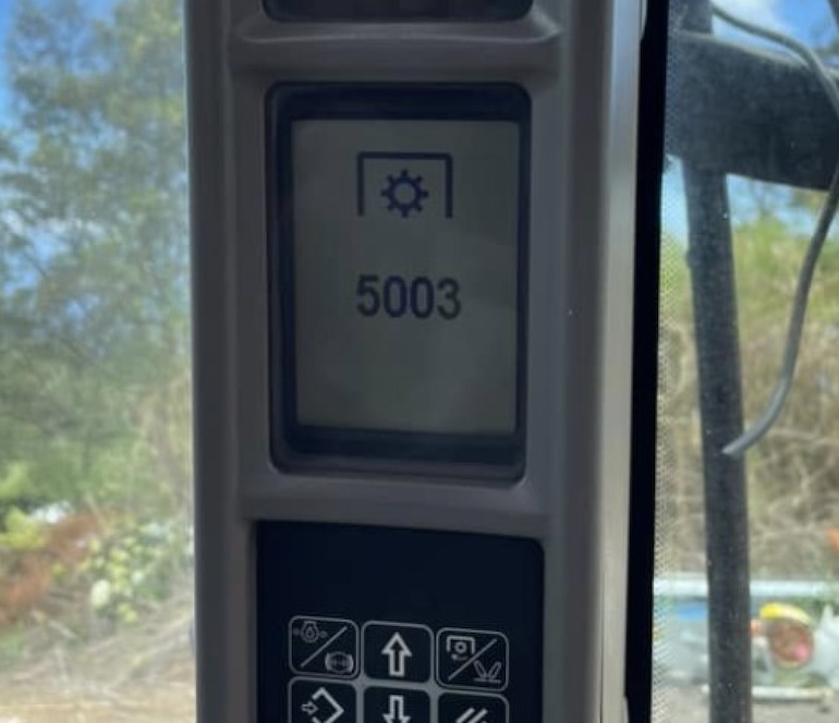
| 5003 | Rear PTO brake circuit open |
| 5004 | Rear PTO brake overheating (not used) |
| 5005 | Brake switch, open circuit |
| 5007 | Rear PTO solenoid jammed |
| 5008 | Overcurrent in the rear PTO solenoid circuit |
| 5024 | Rear PTO not calibrated |
| 5027 | Rear PTO speed sensor circuit open (not implemented) |
| 5033 | Rear PTO in cab N/C switch open circuit |
| 5034 | Rear wing PTO switch open/short to ground. |
| 5035 | Rear Wing PTO Switch Input Short to +12V |
| 5036 | PTO won’t start |
| 5037 | Rear PTO switch in cab stuck closed |
| 5038 | PTO switches in cockpit and fender actuate in 2 seconds |
| 5039 | Incorrect voltage on wing power take-off switch |
| 5040 | Rear wing PTO switches reversed (not used) |
| 5041 | PTO disabled due to false load (not in use) |
| 5042 | PTO control switch short circuit |
| 5099 | Automatic PTO not engaged |
| 6020 | FWD New Switch Error |
| 6021 | FWD solenoid stuck on |
| 6022 | FWD solenoid stuck |
| 6023 | FWD Open circuit solenoid |
| 7014 | Differential lock switch error |
| 7015 | Differential lock solenoid stuck |
| 7016 | Differential Lock Solenoid Stuck On |
| 7017 | Open circuit differential lock solenoid |
| 7018 | Differential lock driver overheating |
| 7024 | Steering angle sensor not calibrated |
| 7031 | Steering Angle Sensor Out of Max Range |
| 7032 | Steering angle sensor out of minimum range |
| 8007 | Front PTO Solenoid Stuck On |
| 8008 | Front PTO Solenoid Circuit Open |
| 8024 | Front PTO not calibrated |
| 8027 | Front PTO speed sensor circuit open |
| 8033 | Front PTO switch in cab, break contact, open circuit |
| 8036 | Front PTO won’t start |
| 8037 | Cab front PTO NO contact stuck closed |
| 8099 | Front PTO option not included |
| 9001 | Front HPL (High Pressure Lift) Potentiometer open circuit. |
| 9002 | Front HPL (High Pressure Lift) Short circuit of the potentiometer. |
| 10001 | Top Lock Solenoid Error |
| 10002 | Lift Solenoid Error |
| 10003 | Lower Solenoid Error |
| 10004 | Front axle potentiometer above threshold |
| 10005 | Front axle potentiometer below threshold |
| 10007 | Boost error, suspension cannot return to set value |
| 10008 | Downshift error, suspension cannot return to set value |
| 10009 | Lower Block Lock Solenoid Error |
| 10024 | Front suspension not calibrated |
| 10099 | Front suspension mode not included |
| 14001 | Rear PTO Speed Short to VCC or Open Circuit |
| 14002 | Rear PTO speed short to ground |
| 14011 | Engine speed sensor short to VCC or open circuit |
| 14012 | Engine speed sensor short to ground |
| 14015 | ADIC 5 volt reference too low – below 4 volts |
| 14016 | ADIC reference voltage too high 5 volts – above 6 volts |
| 14021 | Radar Speed Over Ground short to VCC or open circuit |
| 14022 | Radar Short Ground Speed |
| 14031 | Front PTO Speed Short to VCC or Open Circuit |
| 14032 | Front PTO speed short to ground |
| 14041 | Engine coolant temperature short to VCC or open circuit |
| 14042 | Engine coolant temperature short to ground |
| 14051 | Fuel level sensor short to VCC or open circuit |
| 14052 | Fuel Level Sensor Short to Ground |
| 14061 | Air brake pressure shorted to VCC or option set but sensor not connected |
| 14071 | Front hitch position shorted to 12 or 5 volts |
| 14072 | Front hitch position short to ground or open circuit |
| 14081 | Engine oil pressure short circuit to 12 or 5 volts |
| 14082 | Engine Oil Pressure Short to Ground or Open Circuit |
| 14091 | Output baud rate short to VCC or open circuit |
| 14092 | Transmission output speed short to ground |
| 14100 | Air brake pressure not set |
| 14101 | Fuel contamination sensor Not connected |
| 14900 | Missing (DA/DB/DE/DF) transmission module. |
| 14901 | Engine controller missing (EDC7) |
| 14902 | The (DD/DH) controller accessory (optional) module is missing. |
| 14903 | SCM controller (only GA 12×12) Missing. |
| 14904 | The armrest module (ARU) is missing. (only Steyr 16×16) |
| 14905 | KEYBOARD missing |
| 14906 | Quick Steering Controller (KA) is missing. |
| 14907 | DOG (Display Of Gears) is missing. |
| 15001 | Exceeding the safe operating wheel speed (10 km/h) with the system on or active. The error code is not active, instead the fast turn lamp flashes. |
| 15002 | Steering wheel proximity sensor circuit open. |
| 15003 | Steering wheel proximity sensor short circuit. |
| 15006 | Split LVDT valve, open circuit. |
| 15007 | Short circuit of a split valve LVDT. |
| 15008 | Replace valve Solenoid open circuit. |
| 15009 | Replace Valve Solenoid Short Circuit Through. |
| 15010 | Emergency Switch Failure. |
| 15011 | The maximum switch-on time (5 minutes) has expired. |
| 15012 | Split valve spool stuck open. |
| 15013 | Replace valve or split valve spool stuck closed. |
| 15014 | A split valve spool stuck in the transition zone cannot determine which steering mode the tractor is exactly in. |
| 15015 | Cold oil, temperature below 5 degrees C. Instead, the fast steering light flashes, the error code is not active. |
| 15024 | System not calibrated. |
Case IH Calibration Codes from U1 to U89
| Code | Calibration Code Description |
|---|---|
| CF | Calibration Procedure Completed Successfully |
| CH | Oil Temperature Above 105 Degrees Centigrade |
| CL | Oil Temperature Between 10 and 19 Degrees Centigrade |
| U01 | Front Axle Potentiometer Open Circuit |
| U02 | Front Axle Potentiometer Threshold Is Higher Than The Set Limit |
| U03 | Front Axle Potentiometer Short Circuit Auto Calibration Procedure Will Not Work |
| U04 | Front Axle Potentiometer Threshold Is Lower Than The Set Limit |
| U05 | Front Suspension Is Not Reaching Minimum And Maximum Position During The Auto Calibration Procedure |
| U07 | Suspension Is Stationary During The Raise Command In The Auto Calibration Procedure |
| U08 | Suspension Is Unable To Reach Maximum Height Within 20 Seconds |
| U09 | Suspension Is Stationary During The Lowering Command In The Auto Calibration Procedure |
| U10 | Suspension Is Unable To Reach The Minimum Height Within 25 Seconds |
| U11 | Unable To Calibrate The Suspension |
| U12 | Auto Calibration Procedure Stopped/Vehicle Not Stationary |
| U19 | Oil Temperature Below 10 Degrees Centigrade |
| U21 | Engine RPM Too Low |
| U22 | Engine RPM Too High |
| U23 | Shuttle Lever In Neutral |
| U26 | Clutch Pedal Not Released |
| U31 | Output Speed Sensed – Tractor Moving |
| U33 | Hand Brake Not Applied |
| U34 | Seat Switch Not Activated |
| U36 | Maximum Allowed Clutch Calibration Value Exceeded |
| U37 | Engine RPM Dropped Too Soon |
| U38 | High / Low Synchroniser Calibration Values Out Of Tolerance (Forward) |
| U41 | PTO Speed Detected (PTO Brake Circuit Open or PTO Solenoid Sticking) |
| U43 | PTO Calibration Aborted |
| U45 | No PTO Shaft Movement (PTO Circuit Open) |
| U50 | PTO Twist Sensor Not Calibrated |
| U51 | Unable To Achieve The Required Engine Speed |
| U52 | Constant Engine RPM (CERPM) Switch Switched More Than 3 Times |
| U53 | Remote Levers Used When Calibrating |
| U54 | Steering Used When Calibrating |
| U55 | PTO Engaged When Calibrating |
| U56 | Engine Torque/RPM Sensor Open Circuit |
| U57 | Engine Torque/RPM Sensor Short To Ground |
| U58 | PTO Twist Sensor Open Circuit |
| U59 | PTO Twist Sensor Short To Ground |
| U60 | Out Of Range Calibration Value |
| U81 | No Medium/Reverse Range Synchronizer Movement Sensed |
| U82 | No Low/High Range Synchronizer Movement Sensed |
| U83 | Synchronizer Potentiometer Connectors Swapped |
| U84 | Reverse And High Range Synchronizer Solenoid Connectors Swapped |
| U85 | Medium And Low Range Synchronizer Solenoid Connectors Swapped |
| U86 | Medium/Reverse Range Synchronizer Neutral Error |
| U87 | Low/High Range Synchronizer Neutral Error |
| U88 | Medium/Reverse Range Synchronizer Calibration Values Out Of Tolerance |
| U89 | Low/High Range Synchronizer Calibration Values Out Of Tolerance |
Understanding Case IH Tractor Error / Fault Codes
Case IH tractors are equipped with sophisticated diagnostic systems that monitor various components and systems for potential issues. When a fault or error is detected, the system generates a specific alphanumeric code, known as a Diagnostic Trouble Code (DTC).
These fault codes serve as valuable indicators for diagnosing and troubleshooting problems within the Case IH tractor.
How to Interpret Case IH Tractor Error Codes:
- Code Structure: Case IH DTCs are alphanumeric codes typically consisting of a combination of letters and numbers. Each code represents a specific fault or abnormal condition within a particular system.
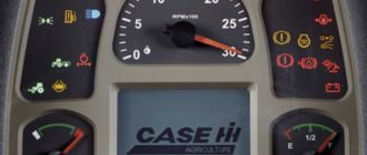
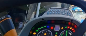
- Accessing Codes: Diagnostic codes can be accessed using specialized diagnostic tools connected to the tractor’s onboard diagnostic port. The tractor’s display screen or instrument panel may also provide access to certain codes.
- Reference Material: Interpretation of DTCs requires reference to the tractor’s service manual or documentation. Each model and series may have unique codes, so it’s crucial to consult the correct reference material.
- Diagnostic Tools: Trained technicians often use advanced diagnostic tools to retrieve and interpret DTCs accurately. These tools enable in-depth analysis and troubleshooting of the specific components or systems indicated by the codes.
Common Case IH Tractor Error Codes:
While the specific codes can vary between models, some common types of DTCs include those related to:
- Engine malfunctions
- Transmission issues
- Hydraulic system faults
- Electrical system problems
- Sensor or sensor circuit errors
Benefits of Understanding DTCs:
- Timely Diagnosis: Swift identification of issues allows for prompt troubleshooting and repairs. Minimizes downtime by addressing problems before they escalate.
- Precision in Repairs: DTCs guide technicians to the specific area or component requiring attention. Reduces guesswork and ensures accurate repairs.
- Preventive Maintenance: Regularly checking and clearing DTCs as part of maintenance helps prevent potential problems. Enhances overall tractor performance and longevity.
In conclusion, understanding Case IH Tractor Error/Fault Codes is essential for efficient maintenance and troubleshooting. It empowers operators and technicians with the information needed to address issues promptly, keeping the tractor in optimal working condition.
Does this list of tractor error codes also apply to new Case IH models?