John Deere Armrest Controller Unit (ACU) Error Codes, also known as Diagnostic Trouble Codes (DTCs), indicate specific faults or malfunctions detected by the Armrest Controller Unit in John Deere equipment. These error codes help technicians diagnose and address issues efficiently.
These error codes provide insights into the operational status of John Deere equipment, allowing for prompt troubleshooting and resolution of issues to ensure optimal performance and productivity.
List of John Deere ACU Error Codes
| Error Code | Error Description | Code Caused by | Control Unit Response |
|---|---|---|---|
| ACU 000158.04 | ACU Switched Supply Voltage Low | Armrest Control Unit switched supply voltage below 9.0 V. | Function Disabled |
| ACU 000177.17 | Engine Speed Limited Due to Cold Oil | Engine speed commanded above 1500 rpm and transmission oil temperature below -5 °C (23 °F). | Limits engine speed to 1500 rpm. |
| ACU 000237.02 | VIN Security Data Conflict | Vehicle Identification Number (VIN) from other control units is not the same. | Function Degraded |
| ACU 000237.14 | VIN Security Not Enabled | Vehicle Identification Number (VIN) security has not been enabled. | Function Degraded |
| ACU 000237.31 | VIN Security Messages Missing | Vehicle Identification Number (VIN) not received from other control units. | Function Degraded |
| ACU 000581.07 | Transmission Not Responding to Command | PTI not responding to armrest control unit requests. | Defaults to Neutral |
| ACU 000628.02 | ACU EOL Data Fault | End-of-line memory failed at start-up. | Defaults to Neutral |
| ACU 000629.11 | ACU Control Unit Fault | Check of RAM memory failed at start-up. | None |
| ACU 000629.12 | ACU Control Unit Fault | Armrest control unit software failed to execute in allotted time. | Defaults to Neutral |
| ACU 000630.02 | ACU Calibration Fault/Data Invalid | Armrest control unit invalid calibration values or failure of calibration memory. | Function Degraded |
| ACU 000630.13 | ACU Calibration Fault/Not Calibrated | Armrest control unit has never been calibrated or a faulty calibration was saved. | Defaults to Neutral |
| ACU 000974.02 | Hand Throttle Sensor Circuit Voltage Conflict | Hand throttle sensor circuits 1 and 2 voltage conflict. | Function Degraded |
| ACU 000974.03 | Hand Throttle Sensor Circuit Voltage High | Hand throttle sensor circuit voltage high. | Function Degraded |
| ACU 000974.04 | Hand Throttle Sensor Circuit Voltage Low | Hand throttle sensor circuit voltage low. | Function Degraded |
| ACU 001079.03 | ACU Sensor Supply 1 Voltage High | Armrest control unit sensor supply voltage high. | Function Degraded |
| ACU 001079.04 | ACU Sensor Supply 1 Voltage Low | Armrest control unit sensor supply voltage low. | Function Degraded |
| ACU 001080.03 | ACU Sensor Supply 2 Voltage High | Armrest control unit sensor supply voltage high. | Function Degraded |
| ACU 001080.04 | ACU Sensor Supply 2 Voltage Low | Armrest control unit sensor supply 2 voltage low. | Function Degraded |
| ACU 002000.09 | ECU Message Missing | Armrest control unit not receiving required messages from the ECU. | Defaults to idle and disables throttle functions. Commands PARK. |
| ACU 002003.09 | PTI or PTP Message Missing | Armrest control unit not receiving required messages from the PTI or PTP. | Commands PARK. |
| ACU 002020.09 | SFA Message Missing | Armrest control unit not receiving required messages from the SFA. | Limited Vehicle Speed (30 km/h) |
| ACU 002049.09 | CAB Message Missing | Armrest control unit not receiving required messages from CAB. | Defaults to Neutral |
| ACU 523664.02 | Speed Band 1 and 2 Switches Conflict | Speed band 1 and 2 switches are reading same value. | Defaults to Neutral |
| ACU 523923.02 | SCV I Control Lever Switch/Sensor Conflict | SCV I control lever switch and sensor voltage conflict. | SCV I disabled by SCC control unit |
| ACU 523923.03 | SCV I Control Lever Sensor Circuit Voltage High | SCV I control lever sensor voltage high. | SCV I disabled by SCC control unit |
| ACU 523923.04 | SCV I Control Lever Sensor Circuit Voltage Low | SCV I control lever sensor voltage below 0.2V. | SCV I disabled by SCC control unit |
| ACU 523953.02 | AutoPowr/IVT Speed Control Lever Sensor Circuit Conflict | Speed control lever sensor voltages 1 and 2 conflict. | Defaults to Neutral |
| ACU 523953.03 | AutoPowr/IVT Speed Control Lever Sensor Voltage High | Speed control lever sensor voltage high. | Defaults to Neutral |
| ACU 523953.04 | AutoPowr/IVT Speed Control Lever Sensor Voltage Low | AutoPowr/IVT speed control lever sensor circuit voltage low. | Defaults to Neutral |
| ACU 523954.07 | Speed Band 1 Adjustment Fault | Calibration for speed band 1 not valid. | Limited function |
| ACU 523954.11 | Set Speed Adjuster Conflict | Set speed adjuster circuit voltage conflict. | Limited Function |
| ACU 523955.31 | Engine Overload In Manual Mode | Engine load too high in manual mode. | Limited Function |
| ACU 523958.31 | Reversing Ratio Setting Fault | Ratio between forward and reverse set speed is incorrect. | Limited Function |
| ACU 523960.17 | Operator Not Present At Low Speeds | Operator presence not detected at low speeds. | Defaults to Neutral |
| ACU 523960.31 | Operator Not Seated During Reverser Command | Operator not present and direction commanded. | Commands PARK. |
| ACU 523961.02 | Park Engaged While In Gear | Park on while vehicle is in gear. | Defaults to Neutral |
| ACU 523961.07 | Park Lock Engagement Fault | Park state does not match the desired state. | Defaults to Neutral |
| ACU 523962.31 | MFWD Speed Incorrect (AutoPowr/IVT only) | MFWD speed invalid. | Traction Control Disabled |
| ACU 523963.02 | Speed Band 1 Switch/Voltage Conflict | Speed band 1 switch does not match analog voltage. | Limited Function |
| ACU 523966.31 | Transmission Come Home Mode | Transmission come home mode enabled. | Defaults to Come Home Mode |
| ACU 523967.02 | Speed Band 2 Switch/Voltage Conflict | Speed band 2 switch does not match analog voltage. | Limited Function |
| ACU 523968.02 | iTEC™ 1/2 Switch Circuit Conflict | iTEC™ 1/2 switch circuits disagree. | No iTEC™ |
| ACU 523968.03 | iTEC™ 1/2 Switch Circuits Voltage High | All three iTEC™ 1/2 switch inputs are high. | No iTEC™ |
| ACU 523968.04 | iTEC™ 1/2 Switch Circuits Voltage Low | All three iTEC™ 1/2 switch inputs are low. | No iTEC™ |
| ACU 524017.31 | Neutral Switch or Forward Slot Voltage Out Of Range | Switch does not clearly indicate a closed or open position. | Defaults to Neutral |
| ACU 524018.31 | RHR Neutral/Park Transition Fault | Lever position transition too long. | Commands PARK (PARK Position Recoverable). |
| ACU 524019.31 | RHR Neutral/Not-Neutral Transition Fault | Lever position transition longer than 5 seconds. | Lever Not In PARK |
| ACU 524020.31 | Transmission In Gear at Power Up | RHR not in PARK at power up. | Commands PARK. |
| ACU 524021.31 | Multiple Reverser Switches Conflict | One or more reverser lever switches have failed. | Commands PARK (PARK Position Recoverable). |
| ACU 524101.02 | Front Hitch Control Lever Switch/Sensor Circuit Conflict | Front hitch control lever switch conflicts with sensor voltage. | Hitch is disabled |
| ACU 524101.03 | Front Hitch Control Lever Sensor Circuit Voltage High | Front hitch control lever sensor circuit voltage high. | Hitch is disabled |
| ACU 524101.04 | Front Hitch Control Lever Sensor Circuit Voltage Low | Front hitch control lever sensor circuit voltage low. | Hitch is disabled |
| ACU 524102.02 | SCV V Control Lever Switch/Sensor Circuit Conflict | SCV V control lever switch conflicts with sensor voltage. | SCV V disabled by SCC control unit |
| ACU 524102.03 | SCV V Control Lever Sensor Circuit Voltage High | SCV V control lever sensor circuit voltage high. | SCV V disabled by SCC control unit |
| ACU 524102.04 | SCV V Control Lever Sensor Circuit Voltage Low | SCV V control lever sensor circuit voltage low. | SCV V disabled by SCC control unit |
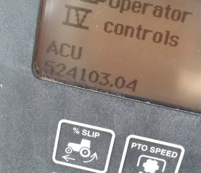
| ACU 524103.02 | SCV IV Control Lever Switch/Sensor Circuit Conflict | SCV IV control lever switch conflicts with sensor voltage. | SCV IV disabled by SCC control unit |
| ACU 524103.03 | SCV IV Control Lever Sensor Circuit Voltage High | SCV IV control lever sensor circuit voltage high. | SCV IV disabled by SCC control unit |
| ACU 524103.04 | SCV IV Control Lever Sensor Circuit Voltage Low | SCV IV control lever sensor circuit voltage low. | SCV IV disabled by SCC control unit |
| ACU 524104.02 | SCV III Control Lever Switch/Sensor Circuit Conflict | SCV III control lever switch conflicts with sensor voltage. | SCV III disabled by SCC control unit |
| ACU 524104.03 | SCV III Control Lever Sensor Circuit Voltage High | SCV III control lever sensor circuit voltage high. | SCV III disabled by SCC control unit |
| ACU 524104.04 | SCV III Control Lever Sensor Circuit Voltage Low | SCV III control lever sensor circuit voltage low. | SCV III disabled by SCC control unit |
| ACU 524105.02 | SCV II Control Lever Switch/Sensor Circuit Conflict | SCV II control lever switch conflicts with sensor voltage. | SCV II disabled by SCC control unit |
| ACU 524105.03 | SCV II Control Lever Sensor Circuit Voltage High | SCV II control lever sensor circuit voltage high. | SCV II disabled by SCC control unit |
| ACU 524105.04 | SCV II Control Lever Sensor Circuit Voltage Low | SCV II control lever sensor circuit voltage low. | SCV II disabled by SCC control unit |
| ACU 524212.02 | Rear Hitch Control Lever Switch/Sensor Circuit Conflict | Rear hitch control lever switch conflicts with sensor voltage. | Hitch is disabled |
| ACU 524212.03 | Rear Hitch Control Lever Sensor Circuit Voltage High | Rear hitch control lever sensor circuit voltage high. | Hitch is disabled |
| ACU 524212.04 | Rear Hitch Control Lever Sensor Circuit Voltage Low | Rear hitch control lever sensor circuit voltage low. | Hitch is disabled |
| ACU 524222.02 | Resume Switch Circuit Conflict | Resume switch ON and OFF shows same value. | No Action |
| ACU 524224.02 | Rear PTO Switch Circuit Conflict | Rear PTO switch ON and OFF shows the same value. | Rear PTO is disabled |
| ACU 524254.31 | Transmission Enable Circuit Fault | Transmission enable circuit voltage incorrect. | No Action |
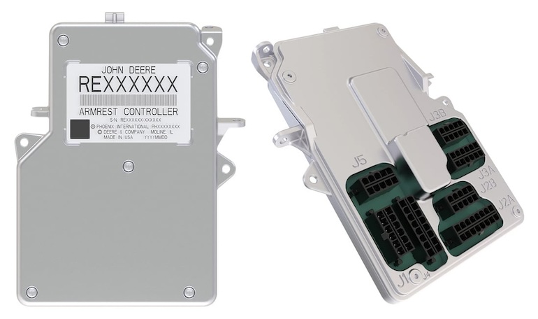
John Deere Armrest Controller Unit
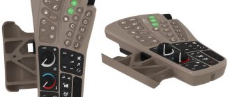
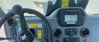
The John Deere Armrest Controller Unit (ACU) is a vital component in modern John Deere agricultural and construction equipment. It serves as a centralized control hub located within the armrest of the operator’s seat. The ACU integrates various functions and systems of the equipment, offering operators convenient access to critical controls and information.
Key features and functions of the Armrest Controller Unit include:
- Control Interface: The ACU houses buttons, switches, dials, and touchscreens that enable operators to control various aspects of the equipment, such as engine speed, transmission settings, hydraulic functions, and implement operations.
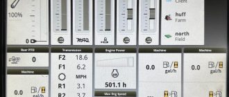
- Information Display: It often includes an integrated display screen or interfaces with the equipment’s main display to provide operators with essential information, including engine performance metrics, diagnostic data, implement status, and navigation guidance.
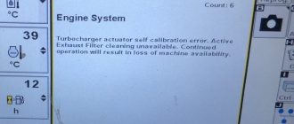
- Diagnostic and Monitoring: The ACU continuously monitors the equipment’s systems and sensors, detecting faults, malfunctions, and performance anomalies. It generates diagnostic trouble codes (DTCs) to alert operators and service technicians to potential issues.
- Integration with Vehicle Systems: The ACU communicates with other electronic control units (ECUs) and subsystems within the equipment, facilitating seamless coordination and operation of different systems, such as the engine, transmission, hydraulics, and implements.
- Customization and Configuration: Operators can often customize the settings and preferences of the ACU to suit their operational needs and preferences. This may include adjusting control sensitivities, display layouts, and user interface settings.
- Operator Comfort and Ergonomics: The design of the armrest and control layout aims to enhance operator comfort and convenience during long hours of operation. Ergonomic placement of controls and intuitive interfaces contribute to improved operator productivity and reduced fatigue.
Overall, the Armrest Controller Unit plays a crucial role in modernizing and enhancing the functionality, efficiency, and ease of use of John Deere equipment, ultimately contributing to improved performance and productivity in agricultural and construction applications.
Can I Clear John Deere ACU Error Codes Myself?
Clearing John Deere Armrest Controller Unit (ACU) error codes yourself may be possible depending on the nature of the error and the capabilities of your equipment.
Before attempting to clear John Deere ACU error codes, ensure that the equipment is parked on level ground, the engine is turned off, and all safety precautions are followed. Clearing error codes incorrectly or without proper understanding of the underlying issues could potentially lead to safety hazards or equipment damage.
Here are some general guidelines:
- Consult the Operator’s Manual: Review the operator’s manual or documentation provided by John Deere for your specific equipment model. It may contain instructions on how to clear certain error codes or diagnostic trouble codes (DTCs).
- Use Diagnostic Tools: Some John Deere equipment may be equipped with diagnostic tools or interfaces that allow operators or service technicians to clear error codes. These tools may include onboard diagnostics systems, diagnostic software, or handheld diagnostic devices.
- Address Root Cause: Clearing error codes without addressing the underlying issue may only temporarily resolve the problem. It’s essential to identify and address the root cause of the error to prevent recurrence. If you’re unsure about the cause of the error or how to fix it, consider consulting a qualified John Deere service technician.
For more complex issues or if you’re unsure about clearing JD error codes yourself, it’s recommended to seek assistance from a certified John Deere dealer or service technician. They have the expertise, tools, and resources to diagnose and resolve equipment issues safely and effectively. Always prioritize safety and proper maintenance procedures when dealing with equipment error codes. If in doubt, consult the manufacturer’s recommendations or seek professional assistance to ensure the proper handling of error codes and maintenance tasks.