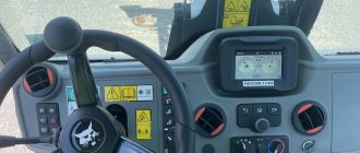
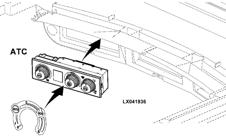
The John Deere Automatic Temperature Control (ATC) unit is a sophisticated system designed to maintain optimal temperature conditions in various components of agricultural and industrial machinery. This system ensures that equipment operates efficiently, reliably, and safely by regulating temperatures within specified ranges.

The ATC unit continuously monitors the temperature of critical components such as the engine, hydraulic systems, and cabin. It adjusts cooling and heating mechanisms to maintain temperatures within optimal ranges, preventing overheating or freezing. The unit integrates multiple sensors that measure temperatures at various points in the machinery. These sensors provide real-time data, enabling the ATC unit to make precise adjustments.
Based on sensor data, the ATC unit automatically adjusts fans, coolant flow, and other temperature control devices. This automation reduces the need for manual intervention and helps maintain consistent performance. The ATC unit also manages the heating, ventilation, and air conditioning (HVAC) system. This ensures a comfortable working environment for operators regardless of external weather conditions.
John Deere Automatic Temperature Control Errors
Diagnostic Trouble Codes (DTCs) related to the ATC unit indicate specific faults or errors within this system. By optimizing temperature control, the ATC unit improves fuel efficiency and reduces wear and tear on components. This leads to lower maintenance costs and extended equipment lifespan.
The ATC unit includes safety mechanisms to prevent equipment damage due to extreme temperatures. If temperatures exceed safe limits, the unit can trigger alarms or shut down the machinery to prevent damage. Here are list of DTCs for John Deere ATC units and their meanings.
JD Error Codes ATC 000168.03 – 001549.04
| Error | Error Name | Error Description |
|---|---|---|
| ATC 000168.03 | Control Unit, Supply Voltage Too High | Triggered if the control unit measures a supply voltage in excess of 16 volts (pin 22, lead 0402, ELX). |
| ATC 000168.04 | Control Unit, Supply Voltage Too Low | Triggered if the control unit measures a supply voltage of less than 9 volts (pin 22, lead 0402, ELX). |
| ATC 000170.03 | B127 Sensor for Inside Air Temperature, Voltage Too High | Triggered if the control unit measures a voltage in excess of 5 volts at the signal input for inside air temperature sensor (B127, lead 2007). |
| ATC 000170.04 | B127 Sensor for Inside Air Temperature, Voltage Too Low | Triggered if the control unit measures 0 volts at the signal input for inside air temperature sensor (B127, lead 2007). |
| ATC 000628.12 | Control Unit Internal Fault | This John Deere error code triggered if an electronic malfunction is registered in the control unit. |
| ATC 000630.02 | Control Unit Internal Fault | This error code triggered if the control unit detects an EEPROM error. |
| ATC 000639.14 | Vehicle CAN BUS, Very High Error Rate | Generated when the control unit receives too many incorrect CAN BUS messages or detects a general problem in the connection to the vehicle CAN BUS. |
| ATC 000871.03 | B130 Sensor for Refrigerant Pressure, Voltage Too High | Triggered if the control unit measures a voltage in excess of 5 volts at the signal input for refrigerant pressure sensor (B130, lead 2019). |
| ATC 000871.04 | B130 Sensor for Refrigerant Pressure, Voltage Too Low | Triggered if the control unit measures 0 volts at the signal input for refrigerant pressure sensor (B130, lead 2019). |
| ATC 000871.13 | B130 Sensor for Refrigerant Pressure, Refrigerant Pressure Out of Valid Range Low | Triggered if the control unit measures less than 1.7 bar (24.6 psi) at the refrigerant pressure sensor (B130, lead 2019). |
| ATC 000876.00 | M02 Compressor Clutch, Current Overload Protection Active at Power Module (HF) PC6 | Triggered if power module (HF) PC6 measures a total amperage in excess of 40 amps at the A1, C1, and D1 outputs. |
| ATC 000876.01 | M02 Compressor Clutch, Power Supply Fault at Power Module (HF) PC6 | Generated if, when compressor clutch (M02) is switched on, power module (HF) PC6 measures less than 3 volts at the supply voltage for the compressor clutch output (lead 0732). |
| ATC 000876.03 | Compressor Clutch Circuit Voltage High | Triggered by a voltage in the A/C compressor clutch circuit that is too high. |
| ATC 000876.04 | M02 Compressor Clutch On, Current Too High at Power Module (HF) PC6 | Triggered if, when compressor clutch (M02) is switched on, power module (HF) PC6 measures in excess of 30 amps at the compressor clutch output (lead 2023). |
| ATC 000876.05 | M02 Compressor Clutch On, No Current Present at Power Module (HF) PC6 | Triggered if, when compressor clutch (M02) is switched on, power module (HF) PC6 measures less than 350 mA at the compressor clutch output (lead 2023). |
| ATC 000876.09 | M02 Compressor Clutch, Incorrect CAN BUS Message from ATC (Power Module (HF) PC6) | Generated if there is a problem transferring data between power module (HF) PC6 and the ATC control unit. |
| ATC 000876.10 | A/C Clutch Overdrive | Triggered if the compressor clutch of the air conditioner is being activated more than six times per minute. |
| ATC 000876.12 | M02 Compressor Clutch Off, Current Present at Power Module (HF) PC6 | Triggered if, with compressor clutch (M02) switched off, power module (HF) PC6 measures in excess of 1 amp at the compressor clutch output (lead 2023). |
| ATC 000876.14 | Compressor Cuts Out Due to Motor Overheats | Triggered if the ATC unit disengages the A/C compressor clutch due to excessive engine heating. |
| ATC 000876.19 | M02 Compressor Clutch, Incorrect CAN BUS Message (Power Module (HF) PC6) | Triggered if the output for switching the compressor clutch is energized by more than one control unit. |
| ATC 000923.00 | M07/M10 Fan Motor, Current Overload Protection Active at Power Module (HF) PC6 | Triggered if power module (HF) PC6 measures a total amperage in excess of 40 amps at one of the fan motor outputs (B1 and/or C3). |
| ATC 000923.01 | M07/M10 Fan Motor, Power Supply Fault at Power Module (HF) PC6 | Generated if, when fan motors (M07 and M10) are switched on, power module (HF) PC6 measures less than 3 volts at the supply voltage for one or both fan motor outputs. |
| ATC 000923.03 | Circulation Blower Motor Circuit High Voltage | Triggered by a high circuit voltage between the circulation blower motor and the blower motor controller. |
| ATC 000923.04 | M07/M10 Fan Motor On, Current Too High at Power Module (HF) PC6 | Triggered if, when fan motors (M07 and M10) are switched on, power module (HF) PC6 measures in excess of 30 amps at one or both fan motor outputs (lead 2043 and/or lead 2047). |
| ATC 000923.09 | M07/M10 Fan Motor, Incorrect CAN BUS Message from ATC (Power Module (HF) PC6) | Generated if there is a problem transferring data between power module (HF) PC6 and the ATC control unit. |
| ATC 000923.12 | M07/M10 Fan Motor Off, Current Present at Power Module (HF) PC6 | Triggered if, with fan motors (M07 and M10) switched off, power module (HF) PC6 measures in excess of 1 amp at one or both fan motor outputs (lead 2043 and/or 2047). |
| ATC 000923.19 | M07/M10 Fan Motor, Incorrect CAN BUS Message (Power Module (HF) PC6) | Triggered if the outputs for switching the fan motors are energized by more than one control unit. |
| ATC 001079.03 | 5volt Power Supply, Voltage Too High | Triggered if the voltage measured at the positive lead (lead 2093) of the power supply to the 5volt components is above 5 volts. |
| ATC 001079.04 | 5volt Power Supply, Voltage Too Low | Triggered if the voltage measured at the positive lead (lead 2093) of the power supply to the 5volt components is less than 0.5 volts. |
| ATC 001551.03 | Pressurizer Blower Motor Circuit Voltage High | Triggered if the voltage in the A/C pressurizer blower motor circuit is too high. |
| ATC 001551.04 | Pressurizer Blower Motor Circuit Voltage Low | Triggered if the voltage in the A/C pressurizer blower motor circuit is too low. |
| ATC 001546.03 | B131 Heater Valve (Potentiometer), Voltage Too High | Triggered if the control unit measures a voltage in excess of 5 volts at the signal input of the potentiometer (heater valve B131, lead 2038). |
| ATC 001546.04 | B131 Heater Valve (Potentiometer), Voltage Too Low | Triggered if the control unit measures 0 volts at the signal input for the heater valve positioning potentiometer (B131, lead 918). |
| ATC 001547.03 | B129 Sensor for Evaporator Core Temperature, Voltage Too High | Triggered if the John Deere control unit measures a voltage in excess of 5 volts at the signal input for evaporator core temperature sensor (B129, lead 2018). |
| ATC 001547.04 | B129 Sensor for Evaporator Core Temperature, Voltage Too Low | Triggered if the control unit measures 0 volts at the signal input for evaporator core temperature sensor (B129, lead 2018). |
| ATC 001548.03 | B128 Sensor for Outlet Temperature, Voltage Too High | Triggered if the control unit measures a voltage in excess of 5 volts at the signal input for outlet temperature sensor (B128, lead 2009). |
| ATC 001548.04 | B128 Sensor for Outlet Temperature, Voltage Too Low | Triggered if the control unit measures 0 volts at the signal input for outlet temperature sensor (B128, lead 2009). |
| ATC 001549.03 | B126 Sensor for Outside Air Temperature, Voltage Too High | Triggered if the control unit measures a voltage in excess of 5 volts at the signal input for outside air temperature sensor (B126, lead 2008). |
| ATC 001549.04 | B126 Sensor for Outside Air Temperature, Voltage Too Low | Triggered if the control unit measures 0 volts at the signal input for outside air temperature sensor (B126, lead 2008). |
JD Error Codes ATC 001549.07 – 600006.13
| Error | Error Name | Error Description |
|---|---|---|
| ATC 001549.07 | B131 Heater Valve, Fault | Triggered if the control unit receives a valid position signal from heater valve potentiometer (B131), but the heater valve cannot be moved to its desired position via the motor’s connecting leads. This indicates a mechanical fault at the heater valve or an open line at the motor’s connecting lines. |
| ATC 001549.13 | B131 Heater Valve, Not Calibrated | Triggered if the heater valve is found to have an invalid calibration, or is not yet calibrated. |
| ATC 001552.03 | Temperature Control, Voltage Too High | Triggered if the control unit measures a voltage in excess of 5 volts at the signal input of the temperature control. This indicates that the internal circuit of the control unit is shorted to a supply lead or is open. |
| ATC 001552.04 | Temperature Control, Voltage Too Low | Triggered if the control unit measures 0 volts at the signal input of the JD temperature control. This indicates a short to ground in the internal circuit of the control unit. |
| ATC 001553.03 | Fan Speed Control, Voltage Too High | This diagnostic trouble code is triggered if the control unit measures a voltage in excess of 5 volts at the signal input of the fan speed control. This indicates that the internal circuit of the control unit is shorted to a supply lead or is open. |
| ATC 001553.04 | Fan Speed Control, Voltage Too Low | Triggered if the control unit measures 0 volts at the signal input of the fan speed control. This indicates a short to ground in the internal circuit of the control unit. |
| ATC 002000.09 | Incorrect CAN BUS Message, Coolant Temperature from ECU | This diagnostic trouble code is generated when a data transfer problem occurs between the ECU and ATC. Reception of the CAN message regarding coolant temperature is intermittent or nonexistent (intermittent reception could be due to a loose wire). |
| ATC 002156.09 | Incorrect CAN BUS Message, Information from Power Module (HF) PC6 | This DTC is generated if there is a problem transferring data between power module (HF) PC6 and the ATC control unit. Reception of one, several or all of the CAN messages transmitted by power module (HF) PC6 is intermittent or nonexistent (intermittent reception could be due to a loose wire). |
| ATC 522343.00 | R17 Resistor at Heated Rear Window, Current Overload Protection Active at Power Module (HF) PC6 | Triggered if power module (HF) PC6 measures an amperage in excess of 40 amps at the output for heated rear window resistor (R17). This indicates that circuit is shorted to ground or that there is a defective component in the circuit. |
| ATC 522343.01 | R17 Resistor at Heated Rear Window, Power Supply Fault at Power Module (HF) PC6 | This error code is generated if, when rearwindow heater is switched on, power module (HF) PC6 measures less than 3 volts at the supply voltage for the rearwindow heater output (lead 0742). |
| ATC 522343.04 | R17 Resistor at Heated Rear Window On, Current Too High at Power Module (HF) PC6 | Triggered if, when rearwindow heater is switched on, power module (HF) PC6 measures in excess of 30 amps in lead 2031. This indicates a short to ground in the circuit. |
| ATC 522343.05 | R17 Resistor at Heated Rear Window On, No Current Present at Power Module (HF) PC6 | Triggered if, when rearwindow heater is switched on, power module (HF) PC6 measures less than 350 mA at the output of resistor (R17; for heated rear window) (lead 2031). This indicates that the circuit is open. |
| ATC 522343.09 | R17 Resistor at Heated Rear Window, Incorrect CAN BUS Message from ATC (Power Module (HF) PC6) | This fault code is generated if there is a problem transferring data between power module (HF) PC6 and the ATC control unit. Reception of one, several or all of the CAN messages transmitted by the ATC to power module (HF) PC6 is intermittent or nonexistent (intermittent reception could be due to a loose wire). |
| ATC 522343.12 | R17 Resistor at Heated Rear Window Off, Current Present at Power Module (HF) PC6 | This JD error is triggered if, with rearwindow heater switched off, power module (HF) PC6 measures in excess of 1 amp at the output of resistor (R17; for heated rear window) (lead 2031). This indicates a short in the circuit or an internal fault in the power module. |
| ATC 522343.19 | R17 Resistor at Heated Rear Window, Incorrect CAN BUS Message (Power Module (HF) PC6) | This John Deere diagnostic trouble code is triggered if the output for switching resistor (R17; for heated rear window) is energized by more than one control unit. |
| ATC 523848.03 | B132 Adjusting Motor for Air Distribution (Potentiometer), Voltage Too High | Triggered if the control unit measures a voltage in excess of 5 volts at the signal input of the potentiometer for the position of the air distribution flaps (adjusting motor B132 for air distribution, lead 2017). This indicates that the circuit is shorted to a supply lead or is open. |
| ATC 523848.04 | B132 Adjusting Motor for Air Distribution (Potentiometer), Voltage Too Low | This John Deere error code is triggered if the control unit measures 0 volts at the signal input of the potentiometer for the position of the air distribution flaps (adjusting motor B132 for air distribution, lead 2017). This indicates a short to ground in the circuit. |
| ATC 523848.05 | B132 Adjusting Motor for Air Distribution, Current Too Low | Triggered if the control unit measures too low an amperage at adjusting motor connecting leads 2028 and/or 2029. This indicates that the circuit is shorted. |
| ATC 523848.06 | B132 Adjusting Motor for Air Distribution, Current Too High | This DTC code is triggered if the control unit measures too high an amperage at adjusting motor connecting leads 2028 and/or 2029. This indicates a short to ground in the circuit. |
| ATC 523848.07 | B132 Adjusting Motor for Air Distribution, Fault | This John Deere code is triggered if the control unit receives a valid position signal from the potentiometer of the air distribution adjusting motor, but the adjusting motor cannot be moved to its desired position via the motor’s connecting leads. This indicates a mechanical fault at the air distribution or an open line at the motor’s connecting lines. |
| ATC 523848.13 | B132 Adjusting Motor for Air Distribution, Not Calibrated | This JD diagnostic trouble code is triggered if the air distribution adjusting motor is found to have an invalid calibration, or is not yet calibrated. |
| ATC 523979.05 | S139 Switch for Heated Rear Window, Current Too Low | Triggered if the control unit measures too low an amperage at the signal input of the indicator light in the rearwindow heater switch (S139, lead 2021). This indicates an interruption in the circuit or, on tractors without the optional ”heated rea. |
| ATC 523979.07 | S139 Switch for Heated Rear Window, Fault | This John Deere DTC is triggered if the control unit receives the engagement signal of the rearwindow heater switch for too long a period of time (S139, lead 2013). This indicates that the switch is jammed or defective, or that there is a problem in the circuit. |
| ATC 524202.03 | B126 Sensor for Ambient Air Temperature (at Rear), Voltage Too High | Triggered if the control unit measures a voltage in excess of 5 volts at the signal input for the rear ambient air temperature sensor (B126, lead 2006). This indicates that the circuit is shorted to a supply lead or is open. |
| ATC 524202.04 | B126 Sensor for Ambient Air Temperature (at Rear), Voltage Too Low | This JD trouble code is triggered if the control unit measures 0 volts at the signal input for the rear ambient air temperature sensor (B126, lead 2006). This indicates a short to ground in the circuit. |
| ATC 524203.03 | B125 Sensor for Ambient Air Temperature (at Front), Voltage Too High | Triggered if the control unit measures a voltage in excess of 5 volts at the signal input for the front ambient air temperature sensor (B125, lead 2001). This indicates that the circuit is shorted to a supply lead or is open. |
| ATC 524203.04 | B125 Sensor for Ambient Air Temperature (Front), Voltage Too Low | Triggered if the control unit measures 0 volts at the signal input for the front ambient air temperature sensor (B125, lead 2001). This indicates a short to ground in the circuit. |
| ATC 524219.02 | B143 Defog Sensor, Frequency out of Valid Range | This fault code is triggered if the control unit registers a frequency from defog sensor (B143, lead 2003) that is out of the valid frequency range (32.26 37.88 Hz). |
| ATC 524219.03 | B143 Defog Sensor, Voltage Too High | This trouble code is triggered if the control unit registers a frequency at the signal input of defog sensor (B143, lead 2003) that indicates that the circuit is shorted to a supply lead or is open. |
| ATC 524219.04 | B143 Defog Sensor, Voltage Too Low | This error code is triggered if the control unit registers a frequency at the signal input of defog sensor (B143, lead 2003) that indicates that the circuit is shorted to ground. |
| ATC 600006.13 | Diagnostic Trouble Code Not Known | Triggered by the CommandCenter (DTI) when the DTI receives an ATC diagnostic trouble code via the CAN BUS that is not stored in the DTI memory. |
Can I Clear John Deere ATC Error Codes Myself?
Clearing John Deere ATC (Automatic Temperature Control) error codes yourself is possible, but it typically requires specific tools and procedures. Here’s a general guideline on how to clear these codes:
- Check the User Manual: Refer to your tractor’s user manual for instructions on how to clear error codes. The manual often provides detailed steps for troubleshooting and resetting the system.
- Diagnostic Tools: Use an appropriate diagnostic tool compatible with John Deere equipment. Tools like the John Deere Service Advisor or other OBD-II diagnostic tools can read and clear error codes. Ensure the tool is compatible with your tractor model.
- Procedure Using Diagnostic Tool:
- Connect the Diagnostic Tool: Plug the diagnostic tool into the tractor’s diagnostic port.
- Read Error Codes: Follow the instructions on the diagnostic tool to read the current error codes.
- Clear Error Codes: Navigate to the option to clear or reset the codes. This will erase the stored error codes from the control unit.
- Manual Reset: In some cases, disconnecting the battery for a short period (usually around 15-30 minutes) can reset the system and clear error codes. However, this method does not address the underlying issues and the codes might reappear if the problem persists.
- Address the Underlying Issue: Ensure that the issues causing the error codes are resolved before clearing them. Simply clearing the codes without fixing the underlying problem will result in the codes reappearing.
- Software Updates: Ensure that the ATC system software is up to date. Sometimes, software updates can resolve persistent error codes.
- Professional Assistance: If you are unable to clear the codes or if the problem persists, consider seeking assistance from a professional John Deere technician. They have the expertise and tools to diagnose and fix more complex issues.
Safety Note: Always follow safety procedures when working on your tractor. Disconnect the battery and follow all manufacturer safety guidelines to prevent accidents or damage.
By following these steps, you should be able to clear ATC error codes from your John Deere tractor. If the problem persists, professional help may be necessary to ensure your JD equipment functions correctly.