- What is a JLG Error / Fault Code (DTC)?
- How Do I Read JLG Error / Fault DTC Codes?
- JLG MEWPs, Lifts & Telehandlers Error List
- JLG DTC Codes (0-0 Help Comments)
- JLG DTCs 211 – 212 (2-1 Power-Up)
- JLG DTCs 221 – 2232 (2-2 Platform Controls)
- JLG DTCs 231 – 233 (2-3 Ground Controls)
- JLG DTCs 251 – 2512 (2-5 Function Prevented)
- JLG DTCs 311 – 312 (3-1 Line Contactor Open Circuit)
- JLG DTCs 321 – 326 (3-2 Line Contactor Short Circuit)
- JLG DTCs 331 – 33407 (3-3 Ground Output Driver)
- JLG DTCs 421 – 423 (4-2 Thermal Limit / SOA)
- JLG DTCs 441 – 33407 (4-4 Battery Supply)
- JLG DTCs 661 – 6635 (6-6 Communication)
- JLG DTCs 671 (6-7 Accessory)
- JLG DTCs 771 – 7742 (7-7 Electric Motor)
- JLG DTCs 811 – 812 (8-1 Tilt Sensor)
- JLG DTCs 821 – 825 (8-2 Platform Load Sense)
- JLG DTCs 991 – 99149 (9-9 Hardware)
- JLG Errors DTC to SPN/FMI Cross Reference Chart
- JLG Scissor Lift Troubleshooting Procedure
- How Do I Clear JLG Error Codes?
Effective troubleshooting and timely maintenance of JLG mobile elevating work platforms (MEWPs) and telehandlers are essential for ensuring operational safety and longevity of the equipment. By following the structured approach to diagnosing and resolving DTCs as outlined, technicians can maintain the lifts in optimal working condition and prevent unexpected downtime.
This guide provides a comprehensive reference for Diagnostic Trouble Codes (DTC) that can be read from the Multifunction Digital Indicator (MDI) on JLG elevating work platforms, scissor lifts and telehandlers. The DTCs are crucial for diagnosing and troubleshooting issues within the lift’s systems. Understanding these codes ensures timely and accurate maintenance, enhancing the safety and efficiency of the equipment.
What is a JLG Error / Fault Code (DTC)?
Fault codes, or DTCs, are digital codes used to diagnose issues in a machine. Each JLG DTC corresponds to a specific malfunction, whether it’s a generic issue or a manufacturer-specific error. These codes provide more detailed information than a general machine alert or indicator symbol, such as a check engine light. Understanding and acting on these codes is essential for addressing issues in your boom lift, mobile elevating work platform or other JLG equipment.
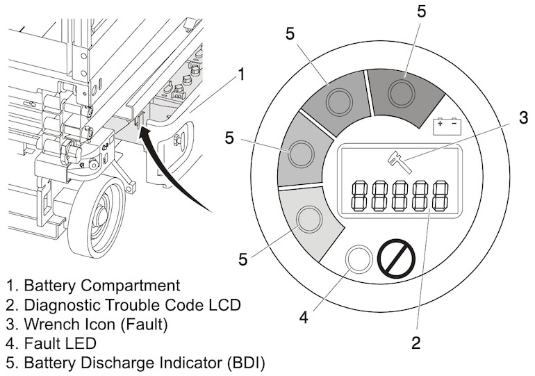
The JLG DTCs are systematically sorted into groups based on their first two digits, which also correspond to the system distress lamp flash code. This methodical grouping facilitates easier identification and troubleshooting of the specific systems or components affected. The groups allow technicians to quickly locate the relevant codes and understand the underlying issues.
How Do I Read JLG Error / Fault DTC Codes?
When a MEWP or telehandler detects a component or system operating outside acceptable limits, the machine activates the corresponding DTC, storing it in its memory. You can retrieve these codes using various methods, including machine analyzers, the ground display on newer equipment models, and telematics portals.
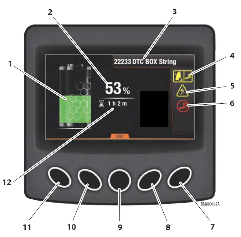
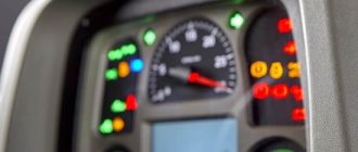
1. Battery Charge; 2. State of Charge Percentage; 3. Scrolling DTC Error Messages; 4. Capacity Zone Indicator; 5. System Distress; 6. Platform Overload; 7. Scroll Page Right Button; 8. Right Navigation Button; 9. Menu Select Button; 10. Left Navigation Button; 11. Scroll Page Left Button; 12. Battery Timer.
The most common way to read a fault code is with a machine analyzer reader. JLG offers three types of analyzers for its equipment: a tethered cable option, a mobile version, a Bluetooth-enabled version (for select models), and a remote option through JLG’s ClearSky fleet management platform. These tools allow you to search for fault codes, enable/disable machine options, and adjust machine parameters for service repairs. With this actionable data, you can make informed decisions about your equipment.
JLG MEWPs, Lifts & Telehandlers Error List
Although preventive and predictive maintenance tasks are crucial to the long-term health and productivity of mobile elevating work platforms (MEWPs) and telehandlers, sometimes machinery stops functioning properly. When that happens, immediate action is necessary. A scissor lift error code is helpful, but only if you take action based on it. To resolve the issue, you need to identify the exact malfunction within the machine.
One way to do this is by looking at Diagnostic Trouble Codes (DTCs), commonly referred to as fault codes.
JLG DTC Codes (0-0 Help Comments)
| DTC | Error Message | Error Description | Check |
|---|---|---|---|
| Error | (Displayed on MDI) | The MDI is powered, but cannot communicate with the control system. | Check the MDI Multifunctional Digital Indicator) connector. Check the diagnostic connector. Refer problem to a qualified JLG mechanic. |
| 001 | EVERYTHING OK | The normal help message in platform mode. Displays on the analyzer only. | |
| 002 | GROUND MODE OK | The normal help message in ground mode. Displays on the analyzer only. | |
| 003 | ALARM SOUNDING – TILTED & ABOVE ELEVATION | Control system senses that the platform is elevated and the vehicle is tilted, and the machine not configured to cutout. | Check that the machine is tilted. If so, lower the platform and reposition the machine to a level surface. Fully stow the platform. The tilt sensor is part of the ground control box. Check that the ground control box is secured to the machine. Check that the pothole protection switches are securely mounted. Check that the elevation angle sensor is securely mounted. |
| 004 | DRIVING AT CUTBACK – ABOVE ELEVATION | The platform is elevated and the machine is driving. | Fully stow the platform. Check that the elevation angle sensor is securely mounted. Check that the pothole protection switches are securely mounted. |
| 005 | DRIVE & LIFT UP PREVENTED – TILTED & ELEVATED | Driving is not possible since the platform is elevated and the chassis is not level. | Check that the machine is tilted. If so, lower the platform and reposition the machine to a level surface. Fully stow the platform. The tilt sensor is part of the ground control box. Check that the ground control box is secured to the machine. Check that the pothole protection switches are securely mounted. Check that the elevation angle sensor is securely mounted. |
| 006 | LIFT UP PREVENTED – MAX HEIGHT ZONE A | The vehicle has reached the maximum height and further lift up motion is not possible. Applicable to 2630ES or 3246ES. | Check that the zone is set appropriately for the platform load. Check that the platform height is at the rated maximum height specification (20’ for 2630 or 26’ for the 3246). Check that the elevation angle sensor is securely mounted. If there are any elevation sensor faults (DTC 251, 252, 2511, or 2512), troubleshoot those first. |
| 007 | DRIVING AT CUTBACK – POTHOLE STILL ENGAGED | While stowed, drive speed is reduced since the control system detected that the pothole protection mechanism failed to retract. | Check for obstructions around the pot-hole protection mechanisms. Check that the PHP switches are securely mounted. |
| 008 | FUNCTIONS LOCKED OUT – SYSTEM POWERED DOWN | After 2 hours without activity, the control system enters a low-power state to preserve battery charge. | Normal operation should resume after power is cycled off then back on. Check batteries charge, condition, etc. |
| 009 | DRIVE PREVENTED – ELEVATED ABOVE DRIVE CUTOUT HEIGHT | The platform is elevated above the calibrated cutout height. | Check that the elevation angle sensor is securely mounted. |
| 0018 | UNDER MOMENT – HYDRAULICS SUSPENDED | The system has detected too little force on the moment pin. If the engine is running, the system suspends all jib, lift up, telescope in, drive, steer and swing functions until the under-moment violation clears | In APU mode, the system suspends swing functions only, but flashes the BCS lamp and sounds the alarm during any command of the jib, lift up, telescope in or swing functions. If the platform is stuck in the air call JLG for help. |
JLG DTCs 211 – 212 (2-1 Power-Up)
| DTC | Error Message | Error Description | Check |
|---|---|---|---|
| 211 | POWER CYCLE | This help message is issued at each power cycle. Displays on the analyzer only. | Normal operation. No check necessary. |
| 212 | KEYSWITCH FAULTY | Both platform and ground modes are selected simultaneously. Defaults to ground mode. | Refer problem to a qualified JLG mechanic. |
JLG DTCs 221 – 2232 (2-2 Platform Controls)
| DTC | Error Message | Error Description | Check |
|---|---|---|---|
| 221 | FUNCTION PROBLEM – HORN PERMANENTLY SELECTED | The horn switch was closed during power-up in platform mode. | Check if the horn switch is damaged, obstructed or jammed. |
| 222 | FUNCTION PROBLEM – INDOOR / OUTDOOR PERMANENTLY SELECTED | The indoor / outdoor (zone A / zone B) switch was closed during power-up in platform mode. | Check if the indoor/outdoor (zone A / zone B) capacity switch is damaged, obstructed or jammed. |
| 223 | FUNCTION PROBLEM – DRIVE & LIFT ACTIVE TOGETHER | The drive and lift inputs are closed simultaneously in platform mode. | Check drive/lift switch for visible damage. |
| 224 | FUNCTION PROBLEM – STEER LEFT PERMANENTLY SELECTED | The steer left switch was closed during power-up in platform mode. | Check if the steer left switch is obstructed or jammed. |
| 225 | FUNCTION PROBLEM – STEER RIGHT PERMANENTLY SELECTED | The steer right switch was closed during power-up in platform mode. | Check if the steer right switch is obstructed or jammed. |
| 226 | ACCELERATOR FAULTY – WIPER OUT OF RANGE | There is a problem with the joystick. | Center joystick and check to see if a power cycle will clear DTC. |
| 227 | STEER SWITCHES FAULTY | The steer left and steer right inputs were closed simultaneously. | Check if the steer switches are damaged, obstructed or jammed. |
| 228 | FUNCTION LOCKED OUT – ACCELERATOR NOT CENTERED | The joystick was not centered at power-up. | Release joystick and allow to center. Check if the joystick is obstructed or jammed. |
| 229 | FUNCTION PROBLEM – TRIGGER PERMANENTLY CLOSED | The trigger switch was closed during power-up in platform mode. | Check if the trigger switch is obstructed or jammed. |
| 2210 | TRIGGER CLOSED TOO LONG WHILE IN NEUTRAL | The trigger switch was closed for more than five seconds while the joystick was centered. | Check if the trigger switch is obstructed or jammed. |
| 2232 | FUNCTION PROBLEM – DRIVE & LIFT BOTH OPEN | The drive and lift inputs are both de-energized in platform mode. | Check if either function is active, if Yes; Refer problem to a qualified JLG mechanic. |
JLG DTCs 231 – 233 (2-3 Ground Controls)
| DTC | Error Message | Error Description | Check |
|---|---|---|---|
| 231 | FUNCTION PROBLEM – LIFT PERMANENTLY SELECTED | The ground control box lift switch was closed up or down, during power-up in ground mode. | Check if the lift switch is obstructed or jammed. |
| 232 | GROUND LIFT UP / DOWN ACTIVE TOGETHER | The lift up / down inputs are closed simultaneously. | Check if the lift switch is obstructed or jammed. |
| 233 | FUNCTION PROBLEM – BRAKE RELEASE PERMANENTLY SELECTED | The manual brake release switch was closed during power-up. | Check if the brake release switch is obstructed or jammed. |
JLG DTCs 251 – 2512 (2-5 Function Prevented)
| DTC | Error Message | Error Description | Check |
|---|---|---|---|
| 251 | ELEV ANGLE SENSOR FAULTY – VOLTAGE OUT OF RANGE | There is a problem with the elevation angle sensor input. | Check that the platform elevation sensor is securely mounted and undamaged. |
| 252 | ELEV ANGLE SENSOR HAS NOT BEEN CALIBRATED | The elevation angle sensor has not been calibrated. | Refer problem to a qualified JLG mechanic. |
| 253 | DRIVE PREVENTED – CHARGER CONNECTED | Driving is not possible while the vehicle is charging. | Check if the charger is connected to off board power source and disconnect if desired. |
| 254 | DRIVE & LIFT UP PREVENTED – CHARGER CONNECTED | Drive or lift is not possible while the vehicle is charging AND is configured to prevent all motion. | Check if the charger is connected to off board power source and disconnect if desired. |
| 255 | PLATFORM OVERLOADED | The load sensing system measured platform load is excessive. | Remove excess weight from the platform. Check that the platform is not caught on something, preventing up or down movement. |
| 256 | DRIVE PREVENTED – POTHOLE NOT ENGAGED | Driving is not possible while elevated since the pot-hole protection system failed to deploy. | Check for obstructions or mechanical problems around the pot-hole protection mechanisms. Check that the PHP switches are securely mounted. |
| 257 | ELEV PROX PERMANENTLY CLOSED – CHECK PROX AND ANGLE ADJUSTMENT | The elevation proximity switch shows the platform to be stowed, while the elevation angle sensor shows the platform to be raised. | The elevation proximity switch is only found on certain older lifts. This switch is not used on current machines so this DTC should not occur. |
| 258 | DRIVE & LIFT PREVENTED – BRAKES ELECTRICALLY RELEASED FOR TOWING | Manual brake release mode is activated with the switch in the battery box near the ground control box. | Push manual brake release switch again or cycle power to clear manual brake release mode. Check if the brake release switch is obstructed or jammed. |
| 259 | MODEL CHANGED – HYDRAULICS SUSPENDED – CYCLE EMS | The model selection has been changed. | Refer problem to a qualified JLG mechanic. |
| 2510 | DRIVE PREVENTED – BRAKES NOT RELEASING | There is a problem with the drive or brake system. | Ensure vehicle is not stuck on something preventing movement. |
| 2511 | ELEV ANGLE SENSOR FAULTY – NOT MOUNTED | The input voltage from the elevation angle sensor indicates the elevation angle sensor is not mounted. | Check that the elevation angle sensor is securely mounted. |
| 2512 | ELEV ANGLE SENSOR NOT DETECTING CHANGE | The input voltage from the elevation angle sensor did not change while vehicle was lifting up. | Check that the elevation angle sensor is securely mounted. |
JLG DTCs 311 – 312 (3-1 Line Contactor Open Circuit)
| DTC | Error Message | Error Description | Check |
|---|---|---|---|
| 311 | OPEN CIRCUIT LINE CONTACTOR | There is a problem with the line contactor. | Refer problem to a qualified JLG mechanic. |
| 312 | CONTACTOR DRIVER PERMANENTLY OFF | There is a problem with the power module line contactor control. | – |
JLG DTCs 321 – 326 (3-2 Line Contactor Short Circuit)
| DTC | Error Message | Error Description | Check |
|---|---|---|---|
| 321 | LINE CONTACTOR MISWIRED ON OR WELDED | There is a problem with the line contactor. | Refer problem to a qualified JLG mechanic. |
| 322 | CONTACTOR DRIVER PERMANENTLY ON | There is a problem with the power module line contactor control. | – |
| 326 | AUXILIARY RELAY – SHORT TO BATTERY | There is a problem with the auxiliary relay contacts or wiring. | – |
JLG DTCs 331 – 33407 (3-3 Ground Output Driver)
| DTC | Error Message | Error Description | Check |
|---|---|---|---|
| 331 | BRAKE SHORT TO BATTERY | A problem has been detected in this function. | Refer problem to a qualified JLG mechanic. |
| 332 | BRAKE OPEN CIRCUIT | A problem has been detected in this function. | – |
| 333 | LIFT UP SHORT TO BATTERY | A problem has been detected in this function. | – |
| 334 | LIFT UP OPEN CIRCUIT | A problem has been detected in this function. | – |
| 335 | LIFT DN SHORT TO BATTERY | A problem has been detected in this function. | – |
| 336 | LIFT DN OPEN CIRCUIT | A problem has been detected in this function. | – |
| 337 | STEER LEFT SHORT TO BATTERY | A problem has been detected in this function. | – |
| 338 | STEER LEFT OPEN CIRCUIT | A problem has been detected in this function. | – |
| 339 | STEER RIGHT SHORT TO BATTERY | A problem has been detected in this function. | – |
| 3310 | STEER RIGHT OPEN CIRCUIT | A problem has been detected in this function. | Refer problem to a qualified JLG mechanic. |
| 3311 | GROUND ALARM SHORT TO BATTERY | A problem has been detected in this function. | – |
| 3312 | LEFT BRAKE SHORT TO BATTERY | A problem has been detected in this function. | – |
| 3313 | RIGHT BRAKE SHORT TO BATTERY | A problem has been detected in this function. | – |
| 3314 | LEFT BRAKE OPEN CIRCUIT | A problem has been detected in this function. | – |
| 3315 | RIGHT BRAKE OPEN CIRCUIT | A problem has been detected in this function. | – |
| 33297 | LEFT BRAKE – SHORT TO GROUND | A problem has been detected in this function. | – |
| 33298 | STEER LEFT VALVE – SHORT TO GROUND | A problem has been detected in this function. | – |
| 33299 | LINE CONTACTOR COIL – SHORT TO BATTERY | A problem has been detected in this function. | Refer problem to a qualified JLG mechanic. |
| 33302 | NEGATIVE SUPPLY – SHORT TO BATTERY | A problem has been detected in this function. | – |
| 33303 | NEGATIVE SUPPLY – SHORT TO GROUND | A problem has been detected in this function. | – |
| 33304 | RIGHT BRAKE – SHORT TO GROUND | A problem has been detected in this function. | – |
| 33305 | STEER RIGHT VALVE – SHORT TO GROUND | A problem has been detected in this function. | – |
| 33406 | LIFT UP VALVE – SHORT TO GROUND | A problem has been detected in this function. | – |
| 33407 | LIFT DN VALVE – SHORT TO GROUND | A problem has been detected in this function. | – |
JLG DTCs 421 – 423 (4-2 Thermal Limit / SOA)
| DTC | Error Message | Error Description | Check |
|---|---|---|---|
| 421 | POWER MODULE TOO HOT – PLEASE WAIT | The power module has reached thermal cutout. | Power down and allow to cool. Do not operate in ambients over 140°F (60°C). |
| 422 | DRIVING AT CUTBACK – Power MODULE CURRENT LIMIT | The drive portion of the power module has reached thermal limit. | Refer problem to a qualified JLG mechanic. |
| 423 | LIFT UP AT CUTBACK – Power MODULE CURRENT LIMIT | The lift up portion of the power module has reached thermal limit. | – |
| 431 | FUEL SENSOR SHORT TO BATTERY | Fuel sensor short to battery. Indicates that the fuel sensor signal [X002.25] may be shorted to battery. | See DTC 33xx – COMMON STB OR OC PROCEDURE |
| 437 | ENGINE TROUBLE CODE | Engine trouble code. This fault text is followed by the engine’s specific fault code. | This code could represent engine faults like low oil pressure warning, high coolant temperature warning, etc. |
JLG DTCs 441 – 33407 (4-4 Battery Supply)
| DTC | Error Message | Error Description | Check |
|---|---|---|---|
| 441 | BATTERY VOLTAGE TOO LOW – SYSTEM SHUTDOWN | A problem has been detected with the batteries or power module. | Recharge batteries or check for damaged batteries. Check battery charger function. |
| 442 | BATTERY VOLTAGE TOO HIGH – SYSTEM SHUTDOWN | A problem has been detected with the batteries or power module. | May be due to improper battery charging or incorrect voltage batteries being used. |
| 443 | LSS BATTERY VOLTAGE TOO HIGH | A problem has been detected with the load sense system. | May be due to improper battery charging or incorrect voltage batteries being used. |
| 444 | LSS BATTERY VOLTAGE TOO LOW | A problem has been detected with the load sense system. | Recharge batteries or check for damaged batteries. |
| 446 | LOGIC SUPPLY VOLTAGE OUT OF RANGE | The System Module logic supply voltage was measured to be out of normal operating range. | Check for severely discharged battery, loose cables, or for damaged battery. |
| 4421 | LOGIC SUPPLY VOLTAGE OUT OF RANGE | The System Module logic supply voltage was measured to be out of normal operating range. | Refer problem to a qualified JLG mechanic. |
| 4422 | LOGIC SUPPLY VOLTAGE OUT OF RANGE | The System Module logic supply voltage was measured to be out of normal operating range. | – |
JLG DTCs 661 – 6635 (6-6 Communication)
| DTC | Error Message | Error Description | Check |
|---|---|---|---|
| 661 | CANBUS FAILURE – Power MODULE | The control system failed to receive messages from the power module. | Refer problem to a qualified JLG mechanic. |
| 662 | CANBUS FAILURE – PLATFORM MODULE | In platform mode, the control system failed to receive messages from the platform board. | – |
| 663 | CANBUS FAILURE – LOAD SENSING SYSTEM MODULE | With load sensing system enabled, the control system failed to receive messages from the load sensing system module. | – |
| 664 | CANBUS FAILURE – ACCESSORY MODULE | An accessory module has stopped communication. | See accessory module documentation for troubleshooting. |
| 6635 | CANBUS FAILURE – CHASSIS TILT SENSOR | Machine control system lost communication with the machine’s tilt sensor. | Refer problem to a qualified JLG mechanic. |
JLG DTCs 671 (6-7 Accessory)
| DTC | Error Message | Error Description | Check |
|---|---|---|---|
| 671 | ACCESSORY FAULT | An accessory module is reporting a fault. | See accessory module documentation for troubleshooting. |
JLG DTCs 771 – 7742 (7-7 Electric Motor)
| DTC | Error Message | Error Description | Check |
|---|---|---|---|
| 771 | OPEN CIRCUIT DRIVE MOTOR WIRING | The power module detected a problem in the drive motors’ power circuit wiring. | Refer problem to a qualified JLG mechanic. |
| 772 | STALLED TRACTION MOTOR OR Power WIRING ERROR | The power module detected a problem in the drive motors’ power circuit wiring. | – |
| 773 | CAPACITOR BANK FAULT – CHECK Power CIRCUITS | The power module detected a problem in the pump or drive motors’ power circuit wiring. | – |
| 774 | SHORT CIRCUIT FIELD WIRING | The power module detected a problem in the drive motors’ power circuit wiring. | – |
| 775 | OPEN CIRCUIT FIELD WIRING | The power module detected a problem in the drive motors’ power circuit wiring. | – |
| 776 | STALLED PUMP MOTOR OR Power WIRING ERROR | The power module detected a problem in the drive motors’ power circuit wiring. | – |
| 777 | OPEN CIRCUIT PUMP MOTOR WIRING | The power module detected a problem in the drive motors’ power circuit wiring. | – |
| 778 | TRACTION T HIGH – CHECK Power CIRCUITS | The power module detected a problem in the drive motors’ power circuit wiring. | – |
| 779 | TRACTION T LOW – CHECK Power CIRCUITS | The power module detected a problem in the drive motors’ power circuit wiring. | – |
| 7710 | PUMP P HIGH – CHECK Power CIRCUITS | The power module detected a problem in the drive motors’ power circuit wiring. | – |
| 7711 | PUMP P LOW – CHECK Power CIRCUITS | The power module detected a problem in the drive motors’ power circuit wiring. | – |
| 7741 | ARMATURE BRAKING CURRENT TOO HIGH | The power module has detected excessive braking current. | This can be caused by transporting an excessive load on a steep grade. |
| 7742 | FIELD VOLTAGE IMPROPER | The power module detected a problem in the drive motors’ power circuit wiring. | Recycle power on/off, if problem persists; refer problem to a qualified JLG mechanic. |
JLG DTCs 811 – 812 (8-1 Tilt Sensor)
| DTC | Error Message | Error Description | Check |
|---|---|---|---|
| 811 | TILT SENSOR NOT CALIBRATED | The tilt sensor calibration has not been performed. | Refer problem to a qualified JLG mechanic. |
| 812 | NO DATA FROM TILT SENSOR – NOT CONNECTED OR FAULTY | No signal from tilt sensor. | – |
JLG DTCs 821 – 825 (8-2 Platform Load Sense)
| DTC | Error Message | Error Description | Check |
|---|---|---|---|
| 821 | LSS CELL #1 ERROR | A problem has been detected with the load sense system. | Refer problem to a qualified JLG mechanic / official dealer |
| 822 | LSS CELL #2 ERROR | A problem has been detected with the load sense system. | – |
| 823 | LSS CELL #3 ERROR | A problem has been detected with the load sense system. | – |
| 824 | LSS CELL #4 ERROR | A problem has been detected with the load sense system. | – |
| 825 | LSS HAS NOT BEEN CALIBRATED | The load sensing system module has not been calibrated. | – |
| 874 | MAINTENANCE INTERVAL | The machine Electronic Control Module (ECM) is programmed with a machine maintenance reminder | The factory default interval for the machine maintenance reminder is 500 hours. The reminder interval can be changed via the “Operator Tools” menu using the handheld analyzer. The reminder interval ranges from 100 hours to 500 hours. |
JLG DTCs 991 – 99149 (9-9 Hardware)
| DTC | Error Message | Error Description | Check |
|---|---|---|---|
| 991 | LSS WATCHDOG RESET | A problem has been detected with the load sense system. | Refer problem to a qualified JLG mechanic |
| 992 | LSS EEPROM ERROR | A problem has been detected with the load sense system. | – |
| 993 | LSS INTERNAL ERROR – PIN EXCITATION | A problem has been detected with the load sense system. | – |
| 994 | LSS INTERNAL ERROR – DRDY MISSING FROM A/D | A problem has been detected with the load sense system. | – |
| 995 | POWER MODULE FAILURE – PERSONALITY RANGE ERROR | A problem has been detected with the power module. | – |
| 996 | POWER MODULE FAILURE – INTERNAL ERROR | A problem has been detected with the power module. | – |
| 997 | POWER MODULE FAILURE – CHECK Power CIRCUITS OR MOSFET SHORT CIRCUIT | A problem has been detected with the power module. | – |
| 998 | EEPROM FAILURE – CHECK ALL SETTINGS | A problem has been detected with the ground board. | – |
| 999 | FUNCTION LOCKED OUT – Power MODULE SOFTWARE VERSION IMPROPER | The power module software version is not compatible with the rest of the system. | – |
| 9910 | FUNCTION LOCKED OUT – PLATFORM MODULE SOFTWARE VERSION IMPROPER | The platform board software version is not compatible with the rest of the system. | – |
| 9911 | FUNCTION LOCKED OUT – LSS MODULE SOFTWARE VERSION IMPROPER | The load sensing system module software version is not compatible with the rest of the system. | – |
| 9912 | POWER MODULE FAILURE – SYSTEM MONITOR | A problem has been detected with the power module. | – |
| 9924 | FUNCTIONS LOCKED OUT – MACHINE NOT CONFIGURED | A new ground board was installed but not configured. | – |
| 9950 9951 9952 9953 9954 9955 9956 9957 9958 9960 9962 9963 9964 9969 9971 9970 99143 99144 99145 99146 99147 99148 99149 |
POWER MODULE FAILURE – INTERNAL ERROR | A problem has been detected with the power module. | Cycle machine power on/off a few times if this doesn’t clear the DTC, refer problem to a qualified JLG mechanic. |
JLG Errors DTC to SPN/FMI Cross Reference Chart
This table presents the JLG DTCs (Diagnostic Trouble Codes), along with their descriptions, Suspect Parameter Number (SPN) codes, and Failure Mode Identifier (FMI) codes.
| DTC | Description | SPN Code | FMI Code |
|---|---|---|---|
| 16 | Crank Never Synced at Start | 636 | 8 |
| 91 | Fuel Pump Low Voltage | 94 | 4 |
| 92 | Fuel Pump High Voltage | 94 | 3 |
| 107 | MAP Low Voltage | 106 | 4 |
| 108 | MAP High Pressure | 106 | 16 |
| 111 | IAT Higher Than Expected | 105 | 15 |
| 112 | IAT Low Voltage | 105 | 4 |
| 113 | IAT High Voltage | 105 | 3 |
| 116 | ECT Higher Than Expected | 110 | 15 |
| 117 | ECT Low Voltage | 110 | 4 |
| 118 | ECT High Voltage | 110 | 3 |
| 121 | TPS 1 Lower Than TPS 2 | 51 | 1 |
| 122 | TPS 1 Signal Voltage Low | 51 | 4 |
| 123 | TPS 1 Signal Voltage High | 51 | 3 |
| 127 | IAT Higher Than Expected | 105 | 0 |
| 129 | BP Low Pressure | 108 | 1 |
| 134 | EGO 1 Open/Inactive | 724 | 10 |
| 154 | EGO 2 Open/Inactive | 520208 | 10 |
| 171 | Adaptive Learn High Gasoline | 520200 | 0 |
| 172 | Adaptive Learn Low Gasoline | 520200 | 1 |
| 182 | Fuel Temp Gasoline Low Voltage | 174 | 4 |
| 183 | Fuel Temp Gasoline High Voltage | 174 | 3 |
| 187 | Fuel Temp LPG Low Voltage | 520240 | 4 |
| 188 | Fuel Temp LPG High Voltage | 520240 | 3 |
| 217 | ECT Higher Than Expected | 110 | 0 |
| 219 | Max Govern Speed Override | 515 | 15 |
| 221 | TPS 2 Signal Voltage Low | 51 | 0 |
| 222 | TPS 2 Signal Low Voltage | 520251 | 4 |
| 223 | TPS 2 Signal High Voltage | 520251 | 3 |
| 261 | Injector Driver 1 Open | 651 | 5 |
| 262 | Injector Driver 1 Shorted | 651 | 6 |
| 264 | Injector Driver 2 Open | 652 | 5 |
| 265 | Injector Driver 2 Shorted | 652 | 6 |
| 267 | Injector Driver 3 Open | 653 | 5 |
| 268 | Injector Driver 3 Shorted | 653 | 6 |
| 270 | Injector Driver 4 Open | 654 | 5 |
| 271 | Injector Driver 4 Shorted | 654 | 6 |
| 336 | Crank Sync Noise | 636 | 2 |
| 337 | Crank Loss | 636 | 4 |
| 341 | Cam Sync Noise | 723 | 2 |
| 342 | Cam Sensor Loss | 723 | 4 |
| 420 | Gasoline Cat Monitor | 520211 | 10 |
| 524 | Oil Pressure Low | 100 | 1 |
| 562 | System Voltage Low | 168 | 17 |
| 563 | System Voltage High | 168 | 15 |
| 601 | Flash Checksum Invalid | 628 | 13 |
| 604 | RAM Failure | 630 | 12 |
| 606 | COP Failure | 629 | 31 |
| 642 | External 5V Reference Low | 1079 | 4 |
| 643 | External 5V Reference High | 1079 | 3 |
| 685 | Power Relay Open | 1485 | 5 |
| 686 | Power Relay Shorted | 1485 | 4 |
| 687 | Power Relay Short to Power | 1485 | 3 |
| 1111 | Fuel Rev Limit | 515 | 16 |
| 1112 | Spark Rev Limit | 515 | 0 |
| 1151 | Closed Loop Multiplier High LPG | 520206 | 0 |
| 1152 | Closed Loop Multiplier Low LPG | 520206 | 1 |
| 1155 | Closed Loop Multiplier High Gasoline | 520204 | 0 |
| 1156 | Closed Loop Multiplier Low Gasoline | 520204 | 1 |
| 1161 | Adaptive Learn High LPG | 520202 | 0 |
| 1162 | Adaptive Learn Low LPG | 520202 | 1 |
| 1165 | LPG Cat Monitor | 520213 | 10 |
| 1171 | LPG Pressure Higher Than Expected | 520260 | 0 |
| 1172 | LPG Pressure Lower Than Expected | 520260 | 1 |
| 1173 | EPR Comm Lost | 520260 | 31 |
| 1174 | EPR Voltage Supply High | 520260 | 3 |
| 1175 | EPR Voltage Supply Low | 520260 | 4 |
| 1176 | EPR Internal Actuator Fault | 520260 | 12 |
| 1177 | EPR Internal Circuitry Fault | 520260 | 12 |
| 1178 | EPR Internal Comm Fault | 520260 | 12 |
| 1612 | RTI 1 loss | 629 | 31 |
| 1613 | RTI 2 Loss | 629 | 31 |
| 1614 | RTI 3 Loss | 629 | 31 |
| 1615 | A/D Loss | 629 | 31 |
| 1616 | Invalid Interrupt | 629 | 31 |
| 1625 | Shutdown Request | 1384 | 31 |
| 1626 | CAN Tx Failure | 639 | 12 |
| 1627 | CAN Rx Failure | 639 | 12 |
| 1628 | CAN Address Conflict Failure | 639 | 13 |
| 1629 | Loss of TSC 1 | 639 | 31 |
| 2111 | Unable to Reach Lower TPS | 51 | 7 |
| 2112 | Unable to Reach Higher TPS | 51 | |
| 2135 | TPS 1/2 Simultaneous Voltages | 51 | 31 |
| 2229 | BP Pressure High | 108 | 0 |
JLG Scissor Lift Troubleshooting Procedure
When multiple DTCs are present, it is recommended to prioritize the troubleshooting process by addressing the DTC with the highest first two digits first. This approach ensures that the most critical or advanced issues are resolved before addressing other less severe codes. Here is a step-by-step procedure for troubleshooting:
- Identify the DTCs: Read the codes displayed on the MDI and note them down.
- Prioritize by Group: Start with the JLG DTC group having the highest first two digits.
- Analyze the Error Message: Refer to the detailed table to understand the specific error message, description, and suggested checks for each code.
- Perform the Recommended Checks: Follow the guidance provided for each DTC, which may include visual inspections, component testing, or specific corrective actions.
- Cycle Machine Power: After performing a check and making any necessary corrections, conclude the process by cycling the machine power using the emergency stop switch. This step is crucial to reset the system and verify if the issue has been resolved.
- Recheck for DTCs: After cycling the power, check the MDI again to see if the JLG DTC persists or if new codes have appeared. Repeat the troubleshooting process if necessary.
How Do I Clear JLG Error Codes?
A JLG error / DTC lookup code will not be cleared until the issue has been resolved and the machine is restored to good working order.
There are two main ways to get information on the issues and how to resolve them:
- Machine’s Service & Maintenance Manual: Refer to the specific details in the manual on how to properly service the machine. Access JLG MEWP and telehandler machine manuals and reference guides online to view the necessary information anytime and anywhere.
- JLG’s Knowledge Base: Search the Knowledge Base article library by DTC or symptom to find solutions to common issues. The Knowledge Base provides DTC descriptions, possible causes, troubleshooting steps, required special tools, and helpful documents to quickly get your JLG machine back in working order.
By understanding and using DTCs effectively, you can promptly address malfunctions and maintain the optimal performance of your MEWPs and telehandlers.


What does error code 874 1-1 mean? (JLG TL1055 Telehandler)
Error Code 874 = “Maintenance Interval” on Certain Telehandlers (TH306D, TH3510D, TH357D, TH408D, TH514D, TL1055D, TL1255D, TL642D, TL943D etc).
The machine Electronic Control Module (ECM) is programmed with a telehandler maintenance reminder. When this reminder activates, it triggers error code 874, “Maintenance Interval”. If your telehandler is not equipped with the optional multifunction display monitor, the code number and the yellow maintenance icon will display on the gauge cluster. The factory default interval for the machine maintenance reminder is 500 hours. The reminder interval can be changed via the “Operator Tools” menu using the handheld analyzer. The reminder interval ranges from 100 hours to 500 hours.
If your telehandler is equipped with the optional display monitor, then the completed maintenance can be recorded using the monitor. Use the access level 2 passcode, 33271, to navigate to “Maintenance” – “Maintenance Log Entry”, and select the maintenance interval that has been completed.
If the machine is not equipped with a display monitor, there are 2 ways to reset the reminder and clear the 874 1-1 error code after performing the required maintenance:
Method 1: Press and hold the two display brightness control buttons simultaneously.
Method 2: Refer to Table 2 for the correct tools for this method. Navigate to “Operator Tools”, select “Confirm Machine Maintenance”, then select “Yes”.
JLG error code 437 – what does it mean?
JLG error 437 is a general engine trouble code indicating that the machine’s control system (ECM) has detected a fault reported by the engine via the J1939 data link. The 437 code itself does not specify the exact issue – it prompts you to look for the accompanying SPN:FMI (Suspect Parameter Number / Failure Mode Identifier) code for details.
Frequently tied to low oil pressure shutdown (especially on Deutz engines). Inspect sensors, oil pressure regulator, wiring, and use JLG manual for precise diagnostics
Error code 101 for E300AJP – what is the problem?
Hi, Alexandra. On a JLG E300AJP electric boom lift, error code 101 usually indicates a system-related or controller communication fault. Error 101 = System fault – often tied to the control system (Ground or Platform Control Module / Control Area Network (CAN) communication error). It may occur if there’s an issue with:
– Poor or loose wiring connection.
– Faulty platform control box or ground control module.
– Voltage supply issue (low battery, weak connection, or corroded terminal).
– CAN bus wiring fault (short, open, or interference).
What to check?
1) Make sure the batteries are fully charged and load-tested.
2) Inspect battery cables and grounds for corrosion or looseness.
3) Check wiring harness connections between the platform and ground control boxes.
4) Look for pinched or damaged wires in the boom cable track.
5) Cycle power (master switch off, wait, then on) and see if the code clears.
I have flash code 3-2 when i turn on ground control, all new contactor board
Do you know your exact JLG model and serial number?
On JLG MEWPs, a flash code 3-2 from the ground control module usually points to a contactor-related or control circuit fault. Flash Code 3-2 – Common Meaning:
– Contactor not responding / welded / stuck. The system expects a change in the contactor status when commanded, but it either stays open or closed.
– Open circuit or short in the contactor coil wiring.
– Incorrect feedback signal from the new contactor board.
Since you’ve already replaced the contactor board, here’s what this code typically means and what you can check next:
1) Verify wiring harness connections – Check plugs between the control board, contactor board, and contactors for bent pins, corrosion, or loose fit. Pay attention to the small feedback wires (not just the large power cables).
2) Check the contactors themselves – Even with a new board, the mechanical contactors may be welded shut or not pulling in. Use a meter to check coil resistance and continuity.
3) Measure coil voltage during activation – When you try to operate, see if the coil is getting proper voltage (usually 24V on JLGs). If voltage is present but the contactor doesn’t move, the contactor is bad. If no voltage is present, trace back to the control board output.
4) Confirm correct replacement board – Some JLG models use different software/hardware revisions. If the board part number doesn’t exactly match your model/serial number, it can throw fault codes.
5) Check ground reference – A weak or floating ground on the platform or chassis can cause “phantom” contactor faults. Make sure all ground lugs are clean and tight.
tenho o erro tower fault – 84152 ja troquei os dois sensores e nada, esta bloqueada a lança
What model of your JLG equipment?