Contents
Dimensions
| Length w/ Blade | 193.5 in (4916 mm) |
| Overall Length w/ Blade and Drawbar | 202.4 in (5139 mm) |
| Length of Track On Ground | 109.5 in (2781 mm) |
| Width Over Tracks | 116 in (2946 mm) |
| Height to Top of Cab / Canopy | 120.7 in. (3065 mm) |
| Height to Top of Exhaust Stack | 124.6 in (3165 mm) |
| Ground Clearance | 14.6 in (371 mm) |
Weight
| Operating Weight | 36576 lb (16625 kg) |
| PAT Blade Weight | 5024 lb (2284 kg) |
| Complete PAT Dozer C-frame Assembly | 2834 lb (1288 kg) |
| Weight of Cab (w/o Air Conditioner) | 2080 lb (945 kg) |
| Weight of Canopy | 1430 lb (650 kg) |
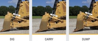
Dozer Blade
| Blade Width | 152 in (3861 mm) |
| Blade Height | 45 in (1143 mm) |
| Blade Lift Height | 35.4 in (899 mm) |
| Blade Digging Depth | 33.4 in (848 mm) |
| Blade Tilt (Uses tilt jack) | 19.1 in (484 mm) |
| Blade Capacity | 4.84 yd3 (3.7 m3) |
| Cut Reach | 5.7 in (144 mm) |
| Cast Reach | 14.4 in (366 mm) |
| Blade Angle (Both directions) | 24° |
| Cutting Edge Angle | 60° |
Undercarriage
| Standard Shoe Size | 34 in (865 mm) |
| Number of Track Rollers per Side | 7 |
| Number of Shoes per Side | 42 |
| Oscillation at Front Roller | 11 in (279 mm) |
| Track Pitch | 7.5 in (190 mm) |
| Track Gauge | 82 in (2083 mm) |
| Length of Track on Ground | 109.5 in (2781 mm) |
| Ground Contact Area | 7446 in2 (4.81 m2) |
| Ground Pressure | 4.91 psi (33.9 kPa) |
Engine Details
| Number of Cylinders | 6 |
| Engine Make | John Deere |
| Engine Model | John Deere 6068T |
| Displacement | 414 cu in (6.8 L) |
| Bore | 4.21 in (107 mm) |
| Stroke | 5.00 in (127 mm) |
| Gross Power | 148 hp (110 kw) |
| Net Power | 140 hp (104 kw) |
| Power Measured @ | 2100 rpm |
| Max Torque | 420 lb ft (570 Nm) |
| Torque Measured @ | 1300 rpm |
| Fuel Consumption, Typical | 3.8 – 5.5 gal/h (14.4 – 20.8 L/h) |
| Lubrication System | Pressure system with full-flow spin-on filter and oil-to-water cooler |
| Air Cleaner | Dual stage dry type with safety element, precleaner, and underhood restriction indicator |
| Muffler | Underhood muffler with vertical exhaust stack |
| Aspiration | Turbocharged (altitude-compensating) |
Operational Specs
| Operating Weight | 36576 lb (16625 kg) |
| PAT Blade Weight | 5024 lb (2284 kg) |
| Max Drawbar Pull | 51000 lb (227 kN) |
| Operating Voltage | 24 V |
| Alternator | 45 amps |
| Battery | 2x 12 V, CCA 950, RC: 190 min |
| Operator Seat | Deluxe suspension cloth seat or Deluxe air suspension vinyl and cloth seat |
| Seat Belt | 3 in (76 mm) with retractors (conforms to SAE J386) |
| Built-in Diagnostics | Fault code retrieval / Onboard diagnostics for monitors, controller(s), wiring, gauges, sensors, etc. |
Transmission
| Type | Automatic, dual-path, hydrostatic transmission |
| Number of Gears | Load sensing feature automatically adjusts speed and power to match changing load conditions |
| Max Forward Speed | 6.8 mph (11 km/h) |
| Max Reverse Speed | 6.8 mph (11 km/h) |
| Motors | Each individually controlled track is powered by a variable displacement piston pump and motor combination |
| Speed Ratios | Independently selectable reverse speed ratios 80%, 100%, 115%, or 130% of forward ground speed |
| Final Drives | Double-reduction, planetary final drives transfer torque loads over three gear sets; mounted independently of track frames and dozer push frames for isolation from shock loads |
| Steering | Single-lever steering, speed, and direction control, and counterrotation. Hydrostatic steering eliminates steering clutches and brakes |
| Service Brakes | Hydrostatic (dynamic) braking stops machine when the direction / steering control lever is moved to neutral, the decelerator is depressed to the end of travel, or the brake pedal is depressed |
| Parking Brake | Exclusive safety feature engages wet, multiple-disc brakes whenever the engine stops, whenever the operator applies the brake pedal, or whenever the park lock lever is placed in the start position |
Hydraulic System
| Type | Open center hydraulics |
| Pump Type | Gear |
| Pump Flow Capacity | 38 gal/min (144 L/min) |
| Relief Valve Pressure | 2000 psi (13790 kPa) |
| Hydraulic Filter, Return Oil | 10 micron |
| Control (Standard dozer blade) | T-bar, two function |
| Control (All-Hydraulic PAT dozer blade) | T-bar, three function |
| Cylinders | Heat-treated, chrome-plated, polished cylinder rods with hardened steel (replaceable bushings) pivot pins |
Service Refill Capacities
| Fuel Tank Capacity | 74 gal (280 L) |
| Engine Oil Capacity (w/ filter) | 5.1 gal (19 L) |
| Cooling System Capacity | 7 gal (26.5 L) |
| Hydraulic Tank Capacity | 18 gal (68 L) |
| Transmission / Hydraulic Oil Capacity | 22 gal (83.3 L) |
| Final Drives Capacity, 1st reduction (each) | 7.35 gal (27.8 L) |
| Final Drives Capacity, 2nd reduction (each) | 3.25 gal (12.3 L) |
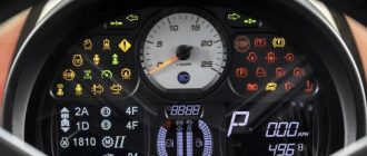
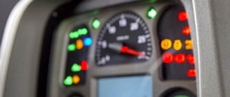
My dash shows: f635, f693, and f691. It no longer will try to move. Help!
Hi, Charles. These error codes often relate to steering sensors and hydrostatic transmission problems.
1) Error Code F635 – Associated with the hydrostatic track speed sensor (often called the “left track speed” or steering sensor). When faulty, the dozer may not move or acts sluggish. Inspect and adjust the sensor gap (~1/8 in), verify wiring integrity, and calibrate the transmission control unit (TCU) via Service Advisor software or onboard calibration procedure.
2) Error Code F693 – Indicates voltage below expected levels on sensors in the steering circuit (typically sensor circuits B20 for lever steering or B10 for pedal steering). You should check connectors and wiring, particularly circuit B20/B10. If persistent, a calibration procedure is required (see transmission calibration steps for lever or pedal steering).
3) Error Code F691 – Reflects voltage above the calibrated range for the same steering sensor circuits (B20 lever or pedal systems). Inspect wiring and connectors, then recalibrate sensors per John Deere Service Advisor procedures.
Fixing issues typically restores full mobility (reverse and forward) and prevents machine from becoming immobile.
1. Inspect Sensor Wiring and Connectors – Access the transmission control module (TCU) and steering sensor locations. Look for loose, corroded, or damaged connectors, especially sensor B15/B20/B10 depending on configuration.
2. Adjust Sensor Gap – For F635: Loosen sensor mounting and fine-tune the gap (~1/8 inch from the speed reference ring) until the fault clears.
3. Recalibrate the Sensors/TCU – Perform John Deere recommended calibration:
– Warm up transmission oil (~100 °F).
– Use decelerator pedal and CAL button sequences as described.
– Walk through control lever/pedal movements until codes clear.
If onboard calibration doesn’t resolve, you’ll likely need John Deere Service Advisor software or dealer support to reprogram or recalibrate the transmission control sensors properly!