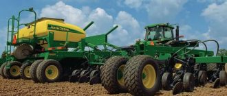
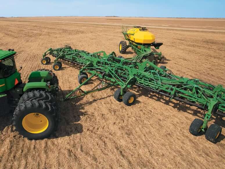
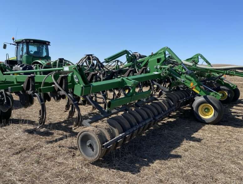
The John Deere 1835 Air Hoe Drill is a high-performance seeding solution designed to deliver precise seed placement and consistent depth control across a variety of field conditions. Built with robust construction and innovative agronomic features, the 1835 is engineered for large-scale producers who demand accuracy, efficiency, and versatility in every pass.
With its floating hitch frame and flexible configurations, this air hoe drill enhances productivity while minimizing soil disturbance, making it ideal for no-till and minimum-till operations. Whether paired with a John Deere air cart or integrated with precision ag technology, the 1835 provides the reliability and control needed to maximize yield potential.
Dimensions
| Road Clearance with Sweep | 16 in (40.6 cm) |
| Transport Width (3-section model) | 20.3 ft (6.2 m), 41 ft (12.5 m) |
| Transport Width (5-section model) | 20.3 ft (6.2 m), 20.5 ft (6.25 m), 50 ft (15.2 m), 61 ft (18.6 m) |
| Nominal Mainframe Width (between wing-fold pivots) | 13.75 ft (4.19 m) |
| Spacing and width #1 | |
|---|---|
| Width | 41 ft (12.5 m) |
| Working Width | 40 ft (12.2 m) |
| Transport Height without Harrow | 18.28 ft (5.57 m) |
| Minimum Temporary Height Reduction with Sweeps | 20 in (508 mm) |
| Weight with Typical Options | 29000 lb (13154 kg) |
| Spacing | 10 in (25.4 cm) |
| Spacing and width #2 | |
| Width | 50 ft (15.2 m) |
| Working Width | 50 ft (15.2 m) |
| Transport Height without Harrow | 15.75 ft (4.8 m) |
| Minimum Temporary Height Reduction with Sweeps | 20 in (508 mm) |
| Nominal inner Wing Width (between wing-fold pivots) | 10.1 ft (3.08 m) |
| Weight with Typical Options | 37575 lb (17044 kg) |
| Spacing | 10 in (25.4 cm) |
| Spacing and width #3 | |
| Width | 61 ft (18.6 m) |
| Working Width | 60 ft (18.3 m) |
| Transport Height without Harrow | 19.02 ft (5.8 m) |
| Minimum Temporary Height Reduction with Sweeps | 20 in (508 mm) |
| Nominal inner Wing Width (between wing-fold pivots) | 13.59 ft (4.14 m) |
| Weight with Typical Options | 41425 lb (18790 kg) |
| Spacing | 10 in (25.4 cm) |
Seed Opener
| Spacing | 10, 12.5 in (25.4, 31.75 cm) |
| Dimensions | 1.25 x 2 x 28 in (31.75 x 50.8 x 711 mm) |
| Tru-Position (angle) | 51° |
| Underframe Clearance | 28 in (71.12 cm) |
| Trip Force 51° | 550 lbf (2.45 kN) |
Fertilizer Opener
| Fertilizer Type | Rolling disk |
| Spacing | 20 in (508 mm) |
| Blade Size | 18 in (457 mm) |
| Fertilizer Compatibility | Anhydrous gas, liquid, dry |
Mainframe
| Centerframe Width | 13.75 ft (4.19 m) |
| Cross Members | 4 x 4 in (10.16 x 10.16 cm) |
| End Tubes | 4 x 4 x 3/8 in (102 x 102 x 9.5 mm) |
| Hitch Pin | 2 in (50.8 mm) |
| Hitch Category | Category IV |
| Seeding Tool Depth Control | Adjustable mechanical stop |
| Mainframe and Wing Flexibility | Diagonal flex |
Fore-Aft Dimensions
| Hitch Pin to Rear of Transport Wheels | 33.2 ft (10.12 m) |
| Lateral Frame Clearance, Opener to Opener | 30 in (76.2 cm) |
| Fore-aft Frame Clearance Between Ranks | 29 in (73.66 cm) |
| Front of Front Cross Member to Front of Rear Rear Member (4 ranks) | 4.83 ft (1.47 m) |
Press Wheels
| Steel Wheels (on 10-in spacing) | 3 x 21 in / 34.7 lb (7.6 x 53.3 cm / 15.7 kg), 4 x 22 in / 35.9 lb (10.2 x 55.9 cm / 16.3 kg) |
| Semi-pneumatic Wheels (on 10-in spacing) | 3 x 21 in / 37 lb (7.6 x 53.3 cm / 16.9 kg), 4 x 21 in / 41.8 lb (10.2 x 53.3 cm / 19 kg), 5.5 x 21 in / 51.6 lb (14 x 53.3 cm / 23.4 kg) |
| Split | 81 lb (36.8 kg) |
Tires
| Tire Code | 2210 | 2215 | 2220 |
|---|---|---|---|
| Wing configuration | Single | Dual | Dual |
| 1835-41,50 (12.50 & 15.20 m) Mainframe duals | 12.5L15 FI LR D | 12.5L15 FI LR D | 33×15.5-16.5 10 PR |
| 1835-41,50 (12.50 & 15.20 m) Wing | 12.5L15 FI LR D | 12.5L15 FI LR D | 31×13.5-15 10PR |
| 1835-61 (18.60 m) Mainframe duals | 12.5L15 FI LR F | 12.5L15 FI LR F | 33×15.5-16.5 10 PR |
| 1835-61 (18.60 m) Wing | 12.5L15 FI LR D | 12.5L15 FI LR D | 31×13.5-15 10 PR |
Tractor Requirements
| John Deere 1835 | 41 ft | 50 ft | 61 ft |
|---|---|---|---|
| Tractor hydraulic SCVs (Minimum) | 3 | 3 | 3 |
| Tractor hydraulic pressure requirement | 2000 psi/min (138 bar/min) | 2200 psi/min (151.7 bar/min) | 2500 psi/min (172.4 bar/min) |
| Tractor Power | 325 hp (242.35 kW) | 400 hp (298.3 kW) | 475 hp (354.2 kW) |
One selective control for frame lift; one selective control for wing fold and transport wheels, one for SFP rockshaft control
Prepare Machine for Leveling Procedure
- Unfold and completely raise machine.
- Properly inflate tires.
- Disengage all depth control shims.
- Adjust Wing Depth shims so half are engaged and half are disengaged.
- Pull forward on level surface to rotate caster wheels to the seeding position. Maintain this position throughout procedure.
- If equipped, raise fertilizer rockshaft.
- Lower until sweeps are 1-2 in (25-51 mm) above ground.