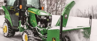
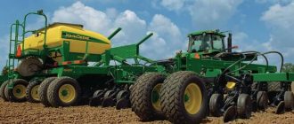
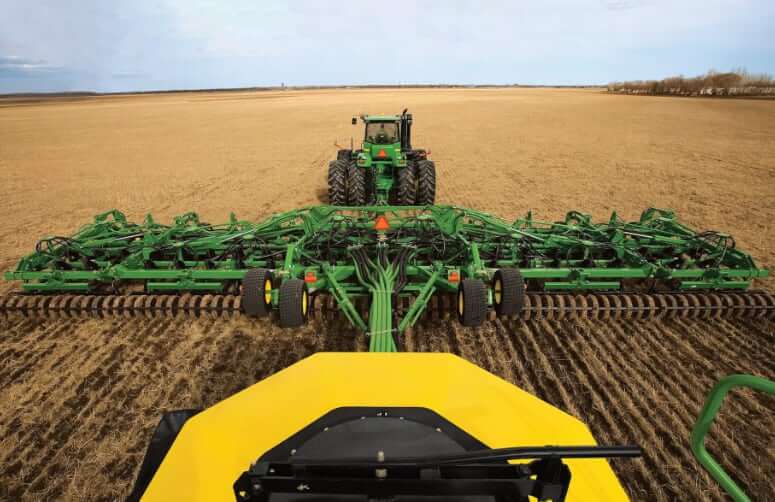
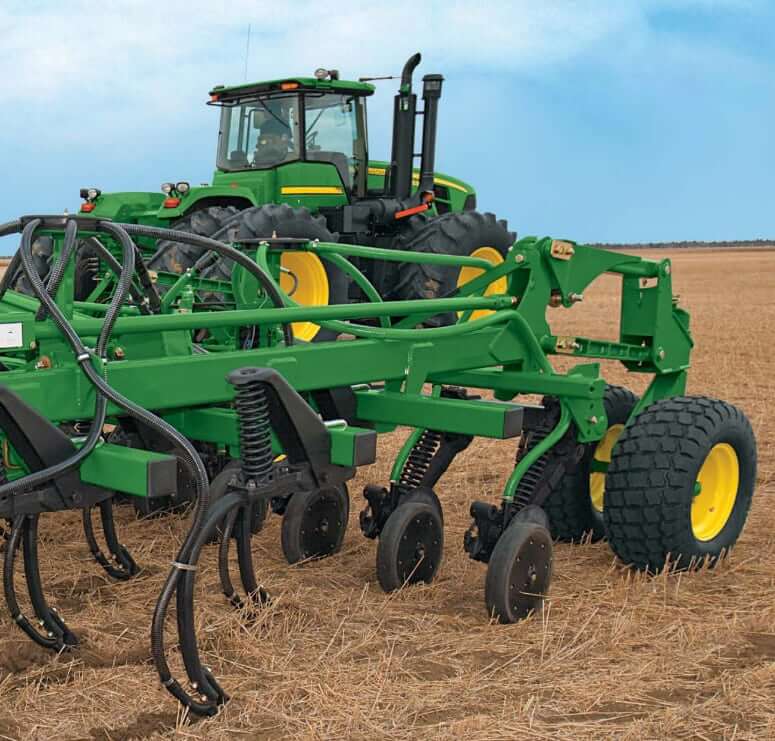
The John Deere 1830 Air Hoe Drill is a versatile and durable seeding implement engineered for efficient seed and fertilizer placement across a wide range of soil and residue conditions. Designed with a rigid-frame configuration and available in various working widths, the 1830 offers precision seed placement through its proven TruPosition standards and adjustable trip force. Ideal for conventional and minimum-till operations, this drill pairs seamlessly with John Deere air carts to provide high-capacity, consistent distribution. Its robust construction, low maintenance requirements, and reliable performance make the 1830 a trusted choice for producers focused on productivity and agronomic accuracy.
Seed Opener
| Spacing | 7.5, 10, or 12.5 in (19.05, 25.40, or 31.75 cm) |
| Dimensions | 1.25 x 2 x 28 in (31.75 x 50.8 x 711 mm) |
| Underframe Clearance | 28 in (71.12 cm) |
| Tru-Position (angle) | 51° |
| Trip force 51° | 550 lbf (2.45 kN) |
Mainframe
| Centerframe Width | 13.75 ft (4.19 m) |
| Cross Members | 4 x 4 in (10.16 x 10.16 cm) |
| End Tubes | 4 x 4 x 3/8 in (102 x 102 x 9.5 mm) |
| Hitch Pin | 2 in (50.8 mm) |
| Hitch Category | Category 4 |
| Seeding Tool Depth Control | Adjustable mechanical stop |
| Mainframe and Wing Flexibility | Diagonal flex |
Harrow
| Harrow Type | Optional two-bar tine-tooth |
Dimensions
| Road Clearance w/ Sweep | 16 in (40.6 cm) |
| Transport Width (3-section model) | 20.3 ft (6.2 m) 41 ft (12.5 m) |
| Transport Width (5-section model) | 20.3 ft (6.2 m) 50.5 ft (15.4 m) 59.4 ft (18.1 m) |
| Nominal Mainframe Width (between wing-fold pivots) | 13.75 ft (4.19 m) |
| Spacing and width #1 | |
|---|---|
| Width | 41 ft (12.5 m) |
| Working Width | 40.62 ft (12.4 m) |
| Transport Height w/ Harrow | 19.22 ft (5.86 m) |
| Transport Height w/o Harrow | 18.28 ft (5.57 m) |
| Minimum Temporary Height Reduction w/ Sweeps | 18 in (457 mm) |
| Weight w/ Typical Options | 24800 lb (11250 kg) |
| Spacing | 7.5 in (19.05 cm) |
| Spacing and width #2 | |
| Width | 50 ft (15.2 m) |
| Working Width | 50.62 ft (15.4 m) |
| Transport Height w/ Harrow | 16.11 ft (4.91 m) |
| Transport Height w/o Harrow | 15.54 ft (4.74 m) |
| Minimum Temporary Height Reduction w/ Sweeps | 20 in (50.8 cm) |
| Nominal Inner Wing Width (between wing-fold pivots) | 10.1 ft (3.08 m) |
| Weight w/ Typical Options | 32850 lb (14900 kg) |
| Spacing | 7.5 in (19.05 cm) |
| Spacing and width #3 | |
| Width | 61 ft (18.6 m) |
| Working Width | 59.37 ft (18.1 m) |
| Transport Height w/ Harrow | 18.13 ft (5.53 m) |
| Transport Height w/o Harrow | 18 ft (5.49 m) |
| Minimum Temporary Height Reduction w/ Sweeps | 20 in (508 mm) |
| Nominal Inner Wing Width (between wing-fold pivots) | 12.55 ft (3.82 m) |
| Weight w/ Typical Options | 36000 lb (16330 kg) |
| Spacing | 7.5 in (19.05 cm) |
| Spacing and width #4 | |
| Width | 41 ft (12.5 m) |
| Working Width | 40 ft (12.2 m) |
| Transport Height w/ Harrow | 19.22 ft (5.86 m) |
| Transport Height w/o Harrow | 18.28 ft (5.57 m) |
| Minimum Temporary Height Reduction w/ Sweeps | 18 in (457 mm) |
| Weight w/ Typical Options | 22775 lb (10330 kg) |
| Spacing | 10 in (25.4 cm) |
| Spacing and width #5 | |
| Width | 50 ft (15.2 m) |
| Working Width | 50 ft (15.2 m) |
| Transport Height w/ Harrow | 16.11 ft (4.91 m) |
| Transport Height w/o Harrow | 15.54 ft (4.74 m) |
| Minimum Temporary Height Reduction w/ Sweeps | 20 in (508 mm) |
| Nominal Inner Wing Width (between wing-fold pivots) | 10.1 ft (3.08 m) |
| Weight w/ Typical Options | 29850 lb (13540 kg) |
| Spacing | 10 in (25.4 cm) |
| Spacing and width #6 | |
| Width | 61 ft (18.6 m) |
| Working Width | 61.67 ft (18.8 m) |
| Transport Height w/ Harrow | 19.62 ft (5.98 m) |
| Transport Height w/o Harrow | 18 ft (5.49 m) |
| Minimum Temporary Height Reduction w/ Sweeps | 19 in (483 mm) |
| Nominal Inner Wing Width (between wing-fold pivots) | 13.59 ft (4.14 m) |
| Weight w/ Typical Options | 33825 lb (15343 kg) |
| Spacing | 10 in (25.4 cm) |
| Spacing and width #7 | |
| Width | 41 ft (12.5 m) |
| Working Width | 41.67 ft (12.7 m) |
| Transport Height w/ Harrow | 19.35 ft (5.9 m) |
| Transport Height w/o Harrow | 18.76 ft (5.72 m) |
| Minimum Temporary Height Reduction w/ Sweeps | 18 in (457 mm) |
| Weight w/ Typical Options | 21250 lb (9639 kg) |
| Spacing | 12.5 in (31.75 cm) |
| Spacing and width #8 | |
| Width | 50 ft (15.2 m) |
| Working Width | 50 ft (15.2 m) |
| Transport Height w/ Harrow | 16.11 ft (4.91 m) |
| Transport Height w/o Harrow | 15.85 ft (4.83 m) |
| Minimum Temporary Height Reduction w/ Sweeps | 20 in (508 mm) |
| Nominal Inner Wing Width (between wing-fold pivots) | 10.1 ft (3.08 m) |
| Weight w/ Typical Options | 27450 lb (12451 kg) |
| Spacing | 12.5 in (31.75 cm) |
| Spacing and width #9 | |
| Width | 61 ft (18.6 m) |
| Working Width | 62.5 ft (19 m) |
| Transport Height w/ Harrow | 20.31 ft (6.19 m) |
| Transport Height w/o Harrow | 19.79 ft (6.03 m) |
| Minimum Temporary Height Reduction w/ Sweeps | 19 in (483 mm) |
| Nominal Inner Wing Width (between wing-fold pivots) | 13.59 ft (4.14 m) |
| Weight w/ Typical Options | 31575 lb (14322 kg) |
| Spacing | 12.5 in (31.75 cm) |
Fore-Aft Dimensions
| Hitch Pin to Rear of Transport Wheels | 32.67 ft (9.95 m) |
| Lateral Frame Clearance, Opener to Opener | 30 in (76.2 cm) |
| Fore-aft Frame Clearance Between Ranks | 29 in (73.66 cm) |
| Front of Front Cross Member to Front of Rear Cross Member (4 ranks) | 7.25 ft (2.21 m) / 32.67 ft (9.95 m) |
Tires
The correct tires are critical to the overall performance and productivity of an air hoe drill. The 12.5L-15 tire (code 2210 or 2215) brings load-carrying capacity and puncture resistance. For additional capabilities in the following situations, consider optioning up to high-flotation, wide-profile knobby tire option (code 2220): transporting on soft, rural roads; operating in generally wetter, softer field conditions; additional puncture resistance is required. The high-flotation tires (code 2220) provide the best performance in all categories with the exception of tire overlap (pass-to-pass) and replacement tire considerations. The size of the machine will depict whether the mainframe will receive 33×15.5-16.5 or 31×13.5-15 size tires.
| Tire Code | 2210 | 2215 | 2220 |
|---|---|---|---|
| Wing Configuration | Single | Dual | Dual |
| 1830-34 (10.40 m) Mainframe Duals | 12.5L15 FI LR D | 12.5L15 FI LR D | 31×13.5-15 10 PR |
| 1830-34 (10.40 m) Wing | 12.5L15 FI LR D | 12.5L15 FI LR D | 31×13.5-15 10 PR |
| 1830-41 (12.50 m) Mainframe Duals | 12.5L15 FI LR D | 12.5L15 FI LR D | 31×13.5-15 10 PR |
| 1830-41 (12.50 m) Wing | 12.5L15 FI LR D | 12.5L15 FI LR D | 31×13.5-15 10 PR |
| 1830-50 (15.20 m) Mainframe Duals | 12.5L15 FI LR D | 12.5L15 FI LR D | 33×15.5-16.5 10 PR |
| 1830-50 (15.20 m) Wing | 12.5L15 FI LR D | 12.5L15 FI LR D | 31×13.5-15 10 PR |
| 1830-61 (18.60 ) Mainframe Duals | 12.5L15 FI LR F | 12.5L15 FI LR F | 33×15.5-16.5 10 PR |
| 1830-61 (18.60 ) Wing | 12.5L15 FI LR D | 12.5L15 FI LR D | 31×13.5-15 10 PR |
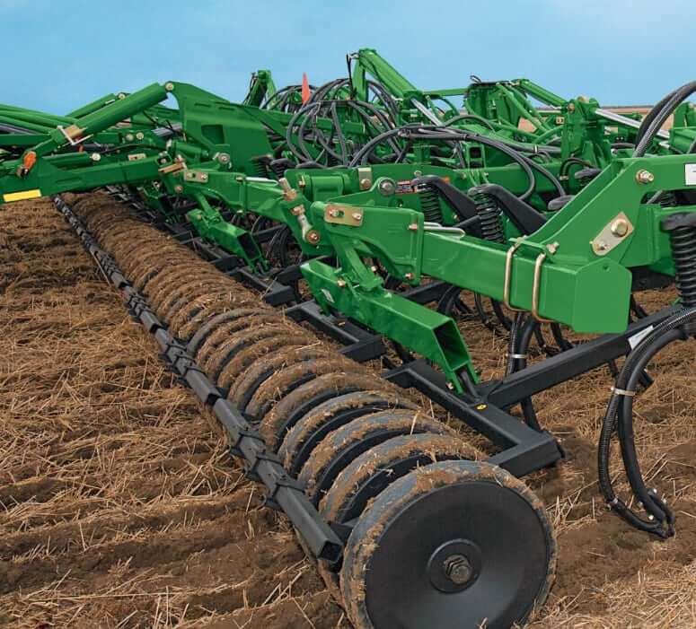
Press Wheels
| Steel (on 7.5-, 10- or 12.5-in spacing) | 3 x 21 in / 34.7 lb (7.6 x 53.3 cm / 15.7 kg) |
| Steel (on 10- or 12.5-in spacing) | 4 x 22 in / 35.9 lb (10.2 x 55.9 cm / 16.3 kg) |
| Semi-pneumatic (on 7.5-, 10- or 12.5-in spacing) | 3 x 21 in / 37 lb (7.6 x 53.3 cm / 16.9 kg) |
| Semi-pneumatic (on 10- or 12.5-in spacing) | 4 x 21 in / 41.8 lb, 5.5 x 21 in / 51.6 lb (10.2 x 53.3 cm / 19 kg, 14 x 53.3 cm / 23.4 kg) |
| Split | 81 lb (36.8 kg) |
Tractor Requirements
| John Deere 1830 | 41 ft | 50 ft | 61 ft |
|---|---|---|---|
| Tractor Hydraulic SCVs (minimum) | Two | Two | Two |
| Tractor Hydraulic Circuit | One selective control for frame lift; one selective control for wing fold and transport wheels | One selective control for frame lift; one selective control for wing fold and transport wheels | One selective control for frame lift; one selective control for wing fold and transport wheels |
| Tractor Hydraulic Pressure | 2000 psi/min (138 bar/min) | 2200 psi/min (151.7 bar/min) | 2500 psi/min (172.4 bar/min) |
| Tractor Power Requirements | 275 hp (205 kW) | 350 hp (261 kW) | 425 hp (317 kW) |
The John Deere 1830 feature a simplified hydraulic system due to a common rockshaft design in the lift circuit. Not only does this tie all sections together ensuring consistent depth from mainframe to wing, it also eliminates 50 to 67 %% of the hydraulic cylinders, reducing the chance of hydraulic failure. Common rockshaft design: no rephasing of hydraulic cylinders; fewer hydraulic components and hoses to maintain; seed with confidence that all air hoe drill sections are seeding at the same depth.